Compressor

A compressor and cylinder bottom technology, applied in the field of compressors, can solve problems such as increased weight and cost, and achieve the effects of improving strength, improving efficiency, and reducing the total number of parts

Inactive Publication Date: 2004-07-14
DAIKIN IND LTD
View PDF1 Cites 1 Cited by
  • Summary
  • Abstract
  • Description
  • Claims
  • Application Information

AI Technical Summary

Problems solved by technology

However, if this is done, the new problem of cost increase will arise while increasing the weight.

Method used


Image

  • Compressor
  • Compressor
  • Compressor

Examples


Embodiment Construction

[0043] Hereinafter, embodiments of the present invention will be described in detail based on the drawings.

[0044] Such as figure 1 As shown, the compressor 10 of this embodiment is a high-pressure dome-type compressor in which an air conditioner is mounted on the compressor, and a high-pressure environment formed by a high-pressure refrigerant inside the compressor 20 is formed.

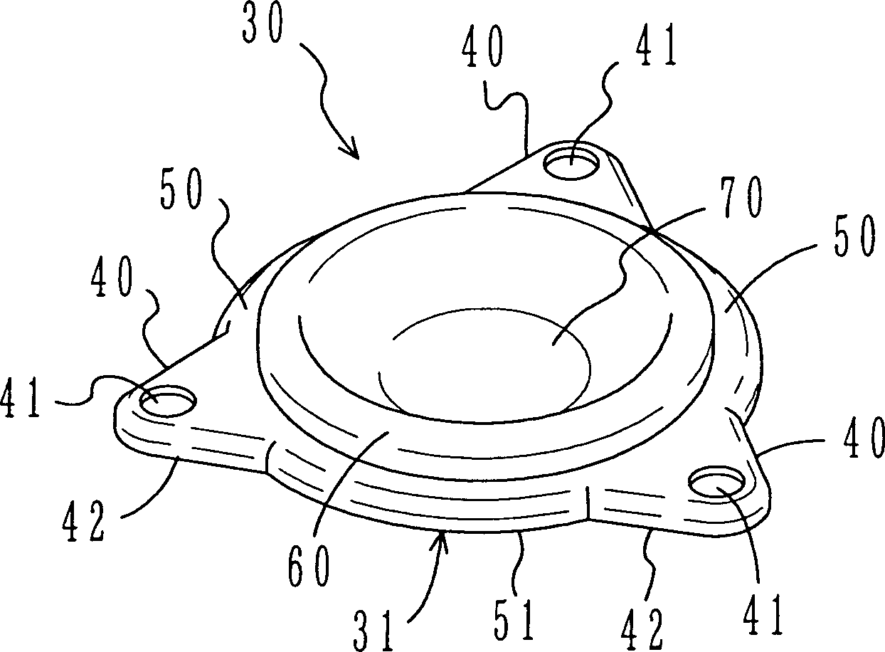
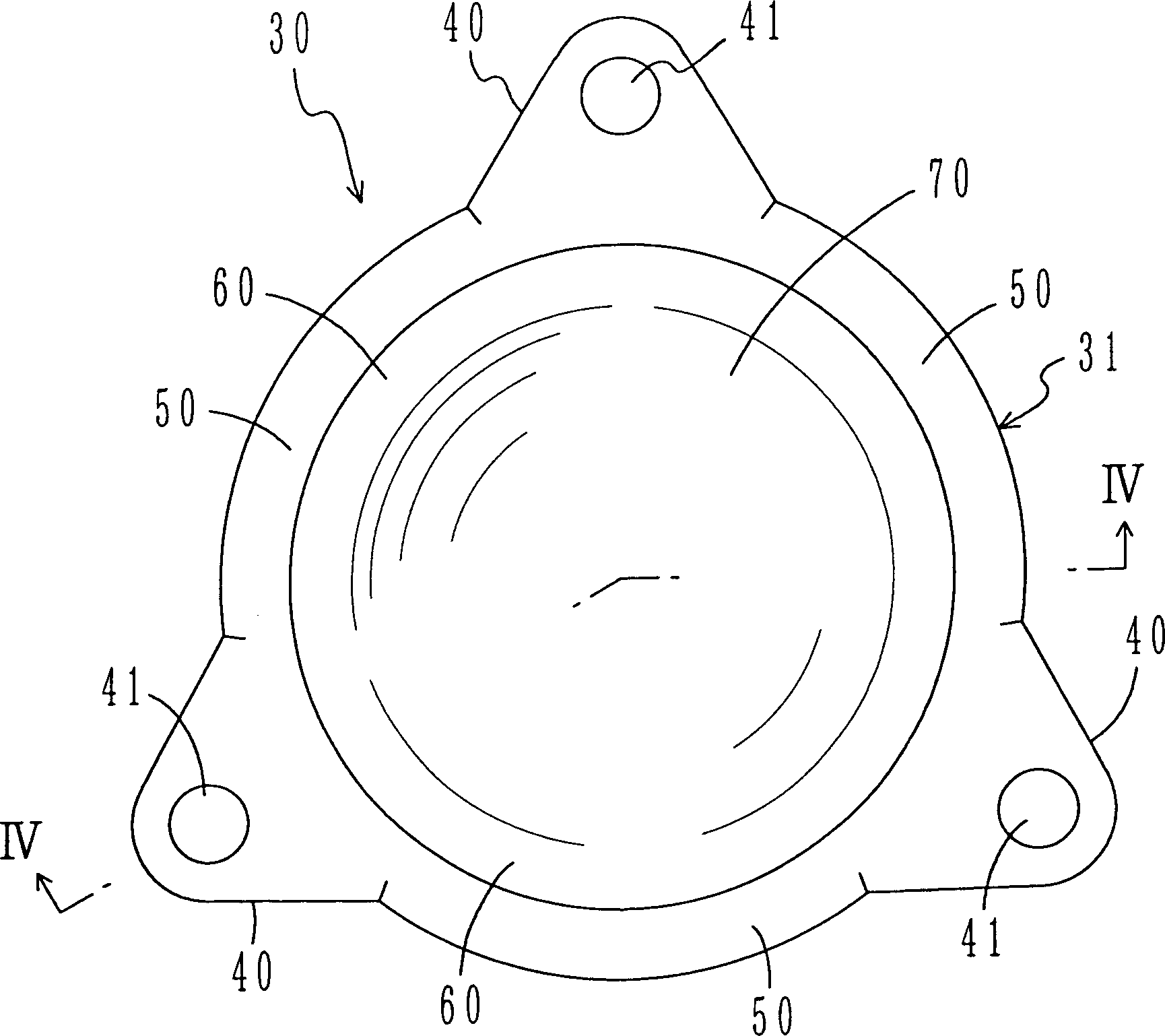
[0045] The above-mentioned compressor 10, not shown in the figure, has a structure in which a motor and a scroll compression mechanism are accommodated in the compressor 20, and the refrigerant is compressed. The above-mentioned compressor 20 includes a barrel body 21 , a barrel cover 22 welded to the upper part of the barrel body 21 , and a barrel bottom 30 welded to the lower part of the barrel body 21 .

[0046] The cylinder body 21 is formed of a vertically long cylindrical member, and is provided with a terminal plate 11 and a discharge pipe 12 . Also, the above-mentioned cylinder cover 22...


PUM


Abstract

The compressor barrel bottom includes one flat outer edge part welded and fixed to the lower part of the barrel bottom, and one annular raised continuous cup-like turned-U part inside the outer edge part. The annular raised cup-like part includes one outer vertical wall, one inner vertical wall and one transitional top wall between the top of the outer vertical wall and the top of the inner vertical wall. The inner vertical wall has arced cross section inclined towards the center of the compressor from top to bottom. The annular raised part has formed concave semi-spherical bottom part in the inner side, and the barrel bottom has installing feet formed integrally with the outer edge part.

Description

technical field [0001] This invention relates to compressors, and more particularly to the construction of the bottom plate of the cylinder. Background technique [0002] Conventionally, as disclosed in Japanese Patent Laid-Open No. 2002-81377 (JP2002-81377A), a compressor installed in an air conditioner or the like has an assembly foot provided at the lower part of the cylinder. And, this mounting leg is fixed to the support table with bolts or the like. [0003] Yet, because above-mentioned assembling foot is installed on this cylinder body after being made separately from cylinder body separately, so just produced the problem that parts quantity is many, and manufacturing price increases. [0004] So, if Figure 7 As shown, it is considered to make the assembly foot c integral with it on the fixed bottom b of the lower end of the barrel a. That is, the above-mentioned cylinder bottom b considers that the cylinder bottom main body d and the assembly foot c having the bol...

Claims


Application Information

Patent Timeline
IPC IPC(8): F04C29/00
Inventor 上川隆司
Owner DAIKIN IND LTD
Why Eureka
Try Eureka