
Sole plate for turbine and power generating plant equipment

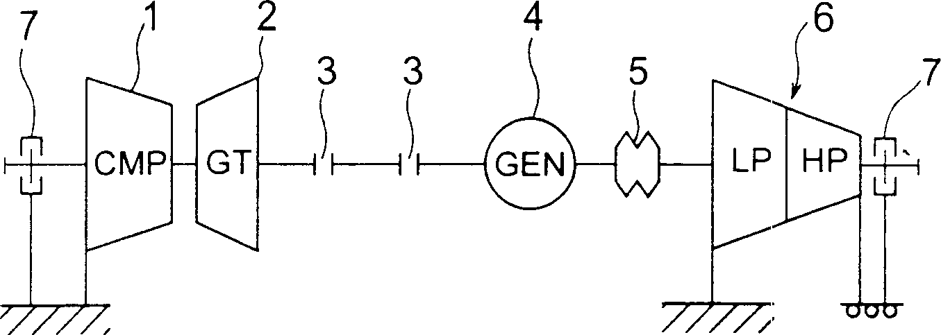
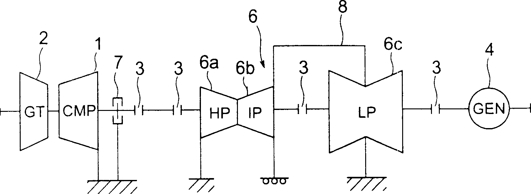
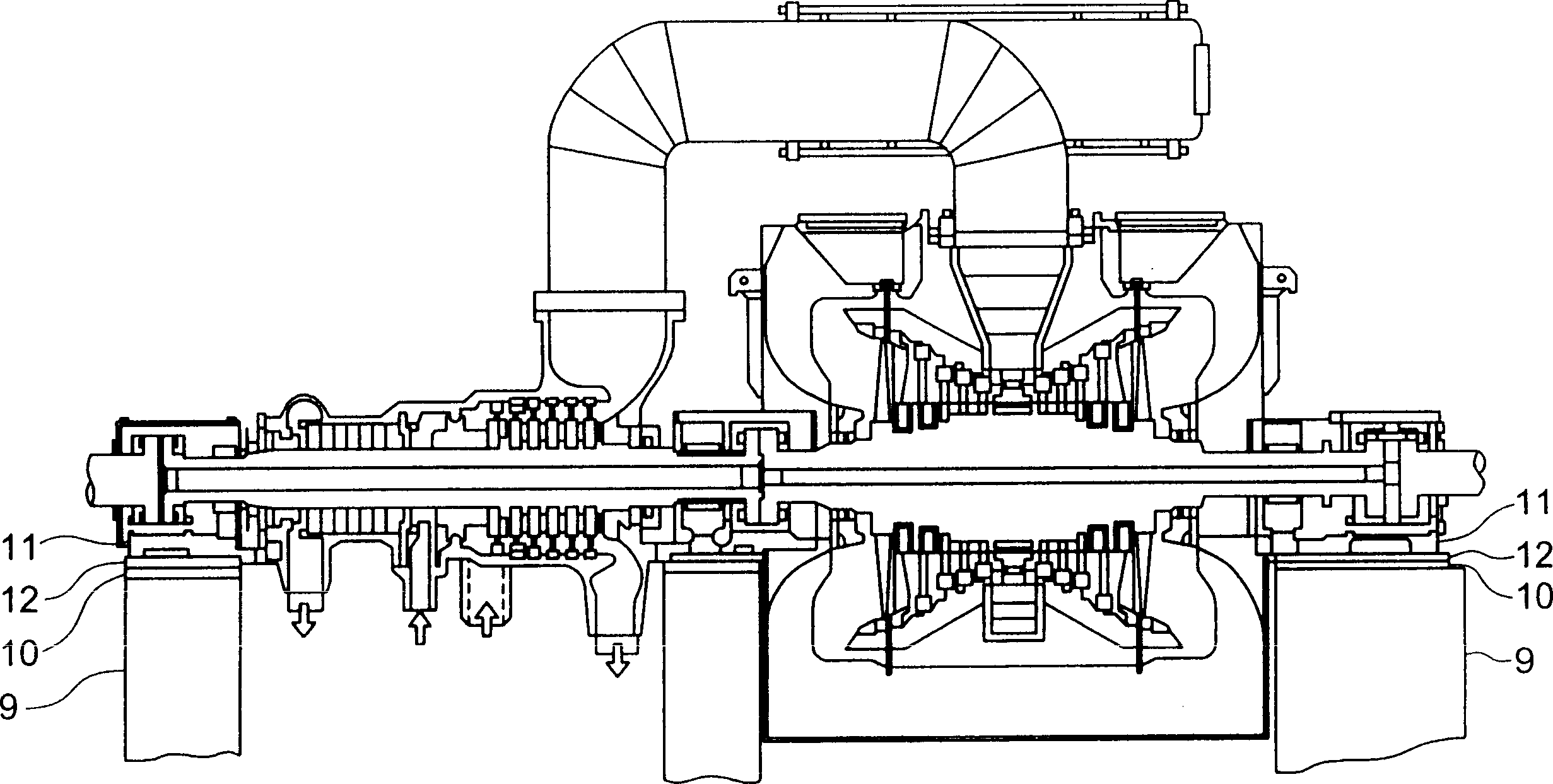
A technology of turbines and bottom plates, applied in mechanical equipment, gas turbine devices, machines/engines, etc., can solve the problems of excessive labor and maintenance and management costs, unable to maintain smooth sliding of the bottom plate for a long time, and achieve the effect of reducing maintenance.

Inactive Publication Date: 2004-07-07
KK TOSHIBA
View PDF0 Cites 4 Cited by
  • Summary
  • Abstract
  • Description
  • Claims
  • Application Information

AI Technical Summary

Problems solved by technology

[0018] In addition, lubricating oil such as grease will solidify and lose its lubricating function when used at high temperature. Therefore, the smooth sliding of the bottom plate cannot be maintained for a long time. The solidified lubricating oil must be removed and new lubricating oil must be injected every certain period of time.
Therefore, a lot of labor and maintenance management costs are required

Method used


Image

  • Sole plate for turbine and power generating plant equipment
  • Sole plate for turbine and power generating plant equipment
  • Sole plate for turbine and power generating plant equipment

Examples


Embodiment 1

[0099] As the bottom plate main body, a bottom plate main body in which grooves are formed on the surface is used. The main body of the bottom plate is made of AISI1045, with a thickness of 100mm, a width of 400mm, and a length of 800mm. In addition, the groove is a V-shaped notch with a depth of 2mm, a width of 4mm, and a length of 400mm.

[0100] Insert this bottom plate main body in the mold, fill the tetrafluoroethylene resin material powder that contains 10% by weight of carbon fiber, at 49MPa (500kgf / cm 2 ) under pressure, so that the resin material powder is impregnated into the V-shaped notch groove of the base plate main body, and a resin layer with a thickness of 2mm is formed on the surface of the base plate main body.

[0101] Thereafter, the chassis main body on which the resin layer was formed was heated at 400° C. for two hours, and the tetrafluoroethylene resin was melt-processed. Thus, a base plate for a turbine having a sliding member made of a carbon fiber-...

Embodiment 2

[0106] As the bottom plate main body, a rectangular plate-shaped bottom plate main body made of AISI1045 with a thickness of 100 mm, a width of 400 mm, and a length of 800 mm was used.

[0107] The holes of each perforated metal plate are formed on the surface of the main body of the bottom plate with a perforated metal plate having a thickness of 1 mm, a hole diameter of 3 mm, and a pitch of 5 mm. The centers are overlapped uniformly, inserted on the surface of the main body of the bottom plate and diffusion bonded in vacuum to form a porous middle layer composed of two perforated metal plates on the surface of the main body of the bottom plate.

[0108] The base plate main body is inserted in the mould, filled with polyimide resin powder containing 10% by weight glass fiber and 5% by weight graphite powder and 10% by weight tetrafluoroethylene resin, at 49MPa (500kgf / cm 2 ) under pressure, the resin material powder is impregnated into the space of the porous intermediate lay...


PUM

PropertyMeasurementUnit
diameteraaaaaaaaaa
thicknessaaaaaaaaaa
widthaaaaaaaaaa

Abstract

A sole plate in use for turbine capable of realizing a smooth sliding on a gland pad used in the mounting portion of power generating plant equipment, effectively suppressing a variation in the alignment of a rotating shaft by a reaction due to thermal expansion and the thrust of a gas turbine, and eliminating a regular maintenance such as filing of lubricating oil, and disposed between the gland pad installed on a base and a turbine support part, comprising a sole plate body made of a metal material disposed on the turbine support part sole and a sliding member made of a material with self-lubricity formed on the surface of the sole plate body on the gland pad side.

Description

technical field [0001] The present invention relates to a base plate for a turbine used for fixing a steam turbine or the like to a foundation, and power plant equipment (electric plant equipment) using the base plate. Background technique [0002] Steam turbines used in large-capacity power generation facilities generally have a divided structure divided into high-pressure, medium-pressure, and low-pressure sections in order to cope with steam expansion, temperature changes, and volume changes. Among such turbines, high-pressure turbines, medium-pressure turbines, and low-pressure turbines are arranged from the higher side of pressure and temperature, and generators are arranged last. [0003] In addition, from the viewpoint of resource saving and harmony with the global environment, a gas turbine (gas turbine) and the steam turbine are combined to perform combined cycle power generation in which the amount of carbon dioxide emitted is reduced. [0004] Single-shaft combin...

Claims


Application Information

Patent Timeline
Patent Type & Authority Applications(China)
IPC IPC(8): C08J5/16F01D25/28F02C7/20
CPCF05C2251/14F02C7/20F01D25/28F05D2300/509
Inventor 龙坦桐木本淳志吉冈洋明藤原敏洋渡边修
Owner KK TOSHIBA
Learn More