Motor with brake

A motor with brake technology, which is applied in the field of motors, can solve the problems of increased processing costs and difficulties in making bosses at the bottom of the tank surface, and achieves the effect of convenient processing and stable axial movement

Inactive Publication Date: 2004-07-07
POSITEC POWER TOOLS (SUZHOU) CO LTD
View PDF0 Cites 5 Cited by
  • Summary
  • Abstract
  • Description
  • Claims
  • Application Information

AI Technical Summary

Problems solved by technology

Since the brake body is a tank-shaped structure, it is very difficult to make a boss at the bottom of the tank surface, which increases the processing cost

Method used


Image

  • Motor with brake
  • Motor with brake
  • Motor with brake

Examples


Embodiment Construction

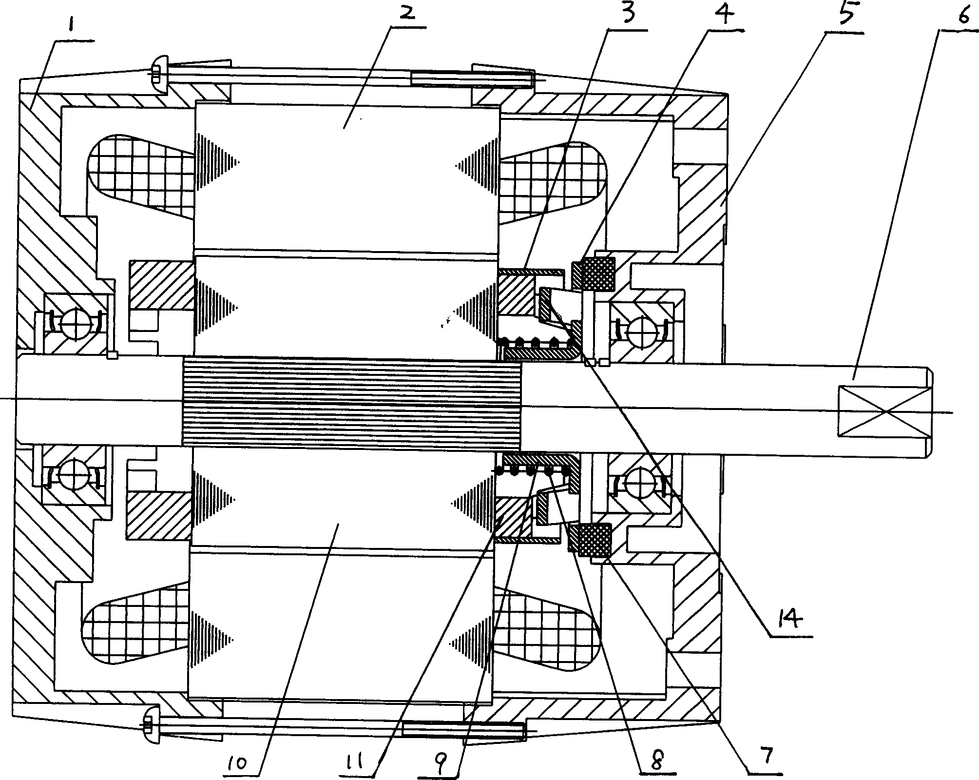
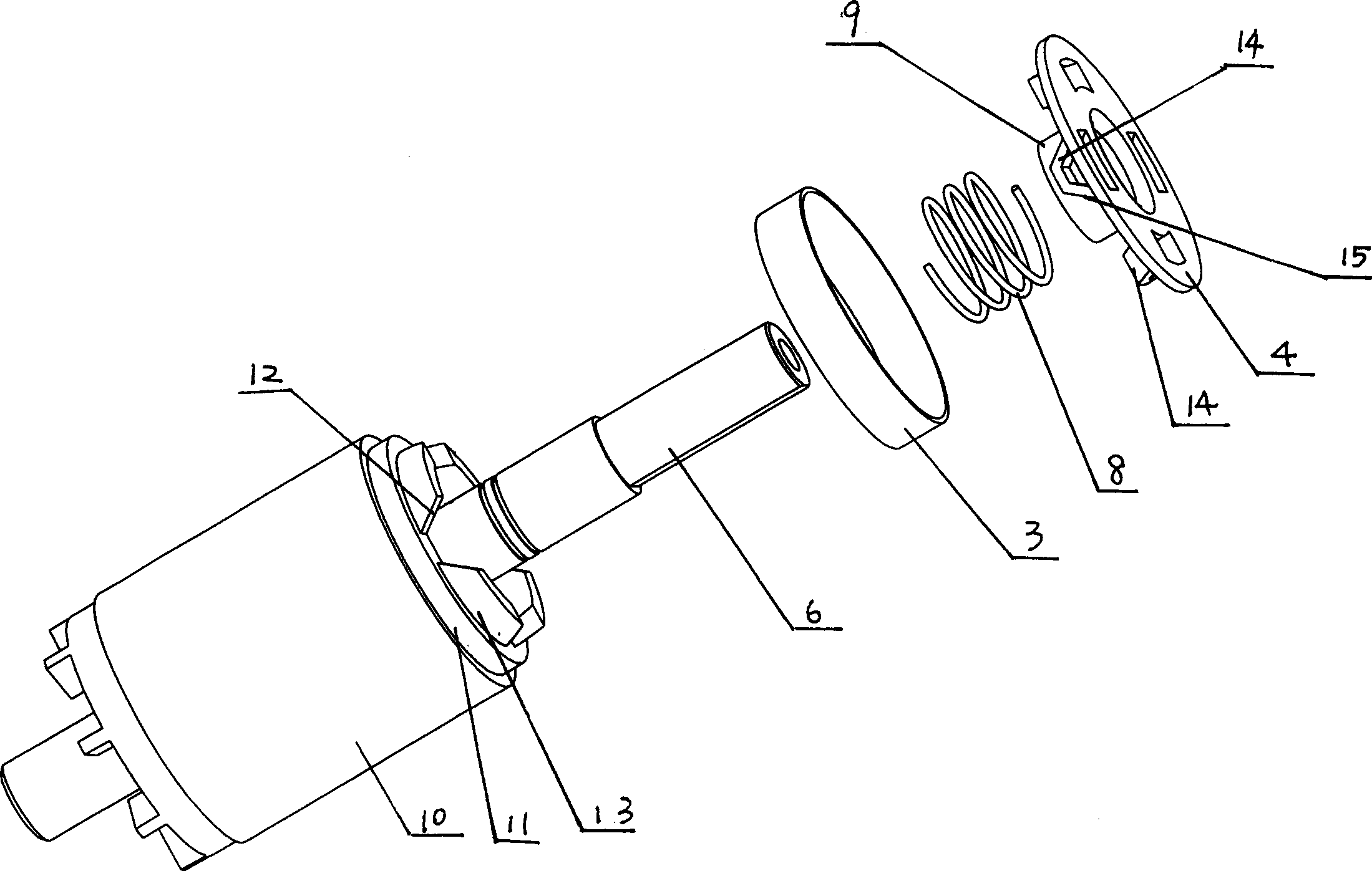
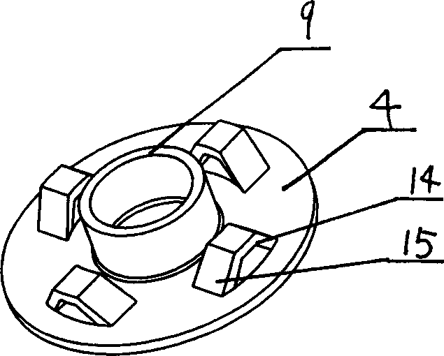
[0016] Referring to the accompanying drawings, a motor with a braking device includes a stator 2, a rotor 10, a shaft 6 fixedly connected to the rotor 10, a short-circuit ring 11 fixedly connected to the end of the rotor 10, and a brake body 4 sleeved on the On the shaft 6 of the brake body 4, the side facing the short-circuit ring 11 is provided with a boss 14 protruding toward the short-circuit ring, and the boss 14 is provided with at least one slope 15, and the short-circuit ring 11 is provided with a boss 13, the projection 13 is provided with at least one wedge surface 12; a friction body 7 is arranged between the brake body 4 and a fixed front end cover 5 relative to the stator 2, and one is used to make the brake body 4 have a tendency The spring 8 leaning against the friction body 7 is arranged between the rotor 10 and the brake body 4, and a magnetically conductive ring 3 is also provided. The magnetically conductive ring 3 and the brake body 4 are of a separate struc...


PUM


Abstract

A motor with brake gear includes: the stator 2 , the rotator 10, the axis 6 fixed on the rotator 10, the short circuit ring fixed on the end of the rotator 10. Its feature is: the outside of the short circuit ring is covered by conducting magnet ring 3, the conducting magnet ring 3 is fission structure with braking body 4, the said conducting magnet ring 3 is fixed between the rotator 10 and braking 4 , can manufacture the braking body independently, the boss of the braking body manufactured is exposed , so it is easy to make it, besides the sleeve of braking body makes braking body move steadily along axis-lead.

Description

technical field [0001] The invention relates to a motor with automatic braking after power failure. Background technique [0002] In the prior art, EP0360779 discloses a device for braking an electric motor with a squirrel-cage rotor, with a sufficiently pot-shaped braking body formed by deep-drawing extension, with its free edge facing the short-circuit ring of the squirrel-cage rotor , there is at least one slope on each boss protruding toward the short-circuit ring, the slope faces the boss on the short-circuit ring provided on the squirrel-cage rotor, each boss has a wedge surface, and the wedge surface is opposite to the squirrel-cage rotor Axis, aligned at the same inclined position as the ramp on the brake body, a brake bushing is provided between the brake body and a component fixed relative to the motor housing, and a brake bush is used to bias the brake body against the brake The spring on the bushing is placed between the brake body and the squirrel cage rotor. ...

Claims


Application Information

Patent Timeline
IPC IPC(8): H02K7/102H02K17/32
CPCH02K17/32H02K7/1026
Inventor 孔钊邹克宁
Owner POSITEC POWER TOOLS (SUZHOU) CO LTD
Why Eureka
Try Eureka