
Piling vessel with pile rotating unit

A technology for a piling ship and a piling frame, which is applied in the field of shipbuilding, can solve the problems affecting the productivity improvement of the piling ship and the proportion of working hours, and achieve the effects of reducing the number of ship transfers, high work efficiency and convenient construction.

Inactive Publication Date: 2004-07-07
郑奇 +1
View PDF0 Cites 3 Cited by
  • Summary
  • Abstract
  • Description
  • Claims
  • Application Information

AI Technical Summary

Problems solved by technology

In short, the proportion of auxiliary working hours of existing piling ships is too large, which is the main reason affecting the productivity of piling ships

Method used


Image

  • Piling vessel with pile rotating unit
  • Piling vessel with pile rotating unit
  • Piling vessel with pile rotating unit

Examples


Embodiment Construction

[0011] The present invention will be further described below in conjunction with the accompanying drawings and embodiments.

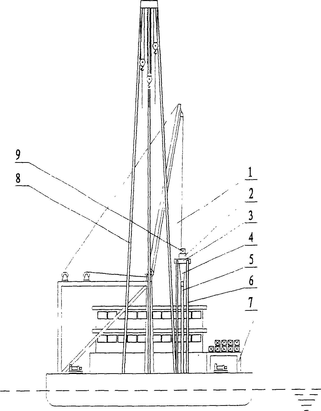
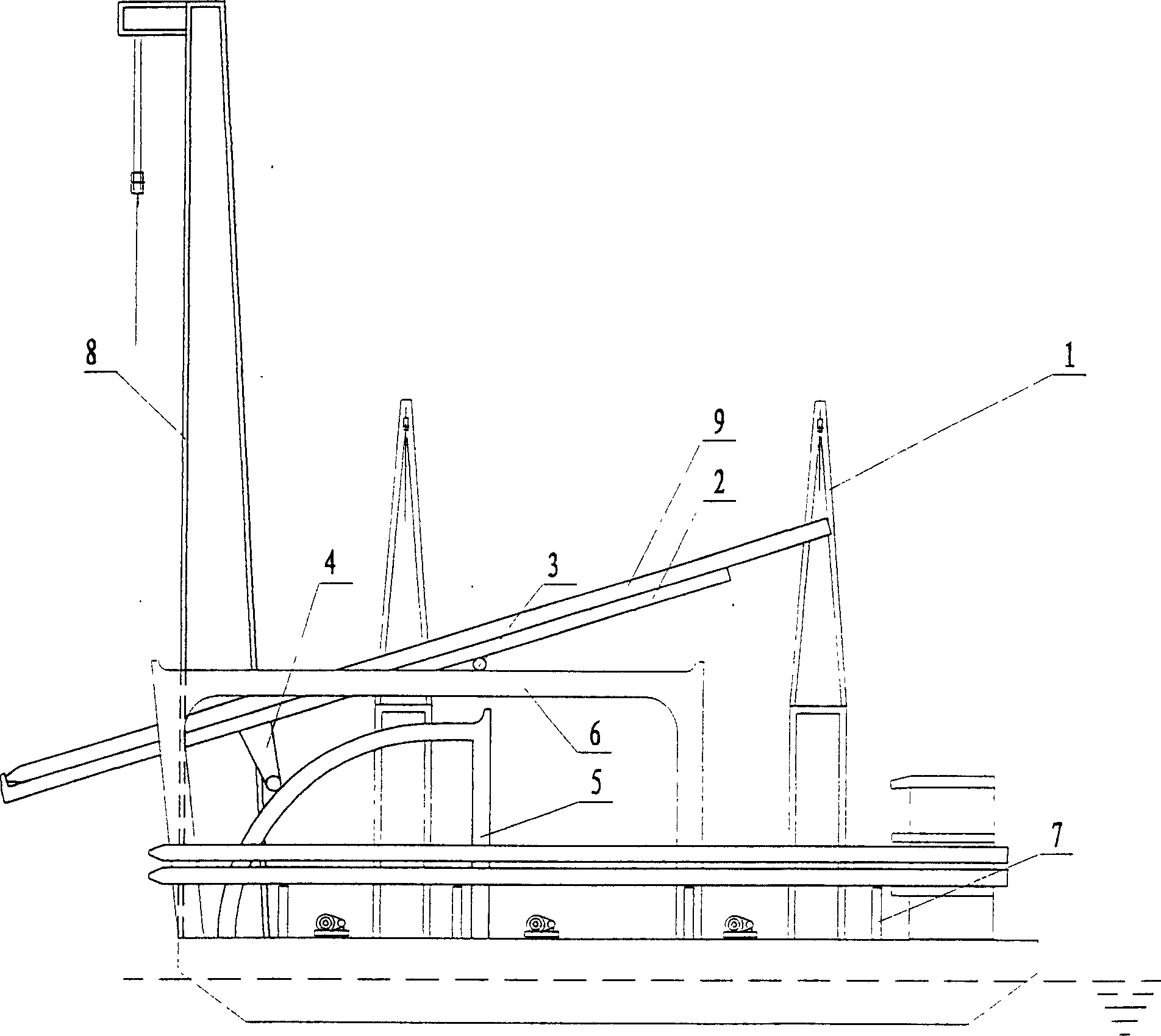
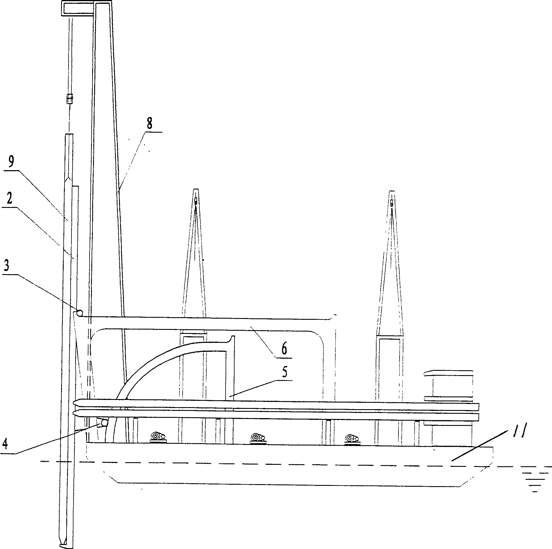
[0012] A piling ship with a piling device, which mainly includes a hull 11, a power system installed in the hull and a luffing pile driving frame 8 installed on the hull. It is different from the prior art in that: the hull 11 is equipped with a piling Device 12, pile storage bracket 7 and pile hanging crane 1, implementing transfer pile device 12 has two outer slideway frames 6, an inner slideway frame 5 and a pile holder frame 2, and the inner slideway frame 5 is placed between two outer slideway frames. Between the slideway frames 6, the pile support frame 2 is placed on the inner slideway frame 5, and there is a leg 4 near the front end at the back of the pile support frame 2, and the support leg 4 rests on the slideway surface of the inner slideway frame 5 There is a crossbeam 3 near the rear end at the back of the pile holder 2, and the crossbeam ...


PUM


Abstract

A pile driving ship features that a pile orientating apparatus, a pile storage mechanism and a pile hoist are installed on it for increasing its productivity by 70% or more.

Description

Technical field: [0001] The invention belongs to the technical field of shipbuilding, in particular to a pile-driving ship with a pile-turning device, and in particular to a pile-turning device added on the pile-driving ship. Background technique: [0002] The piling barge is one of the main construction equipment for water engineering, and the production efficiency of the piling barge plays a decisive role in the entire construction period of the project. A luffing piling ship described in Section 3, Chapter 1, Chapter 1, Chapter 13 of Port Engineering Construction Manual (such as No. ship name). Its composition is the hull, piling frame, luffing oil cylinder, windlass winch, and pile hanging winch. Its shortcomings are as follows. First, each pile driving ship must rely on twisting and anchoring to reach 100 meters away from the pile sinking work area by itself. - 300 meters of piling barge to pick up piles, and then transport them back. Since the slenderness ratio of r...

Claims


Application Information

Patent Timeline
Patent Type & Authority Applications(China)
IPC IPC(8): B63B35/00
Inventor 郑奇钟林贵
Owner 郑奇
Learn More