Mould for extrusion melt tube

A mold and tubular technology, which is applied in the field of molds for extruding tubular molten pipes, can solve problems such as foil pressing pollution

Inactive Publication Date: 2004-06-16
REIFENHAEUSER MASCH DE
View PDF3 Cites 1 Cited by
  • Summary
  • Abstract
  • Description
  • Claims
  • Application Information

AI Technical Summary

Problems solved by technology

[0006] The object of the present invention is to improve molds of the type with vertical melt distribution devices ...

Method used


Image

  • Mould for extrusion melt tube
  • Mould for extrusion melt tube
  • Mould for extrusion melt tube

Examples


Embodiment Construction

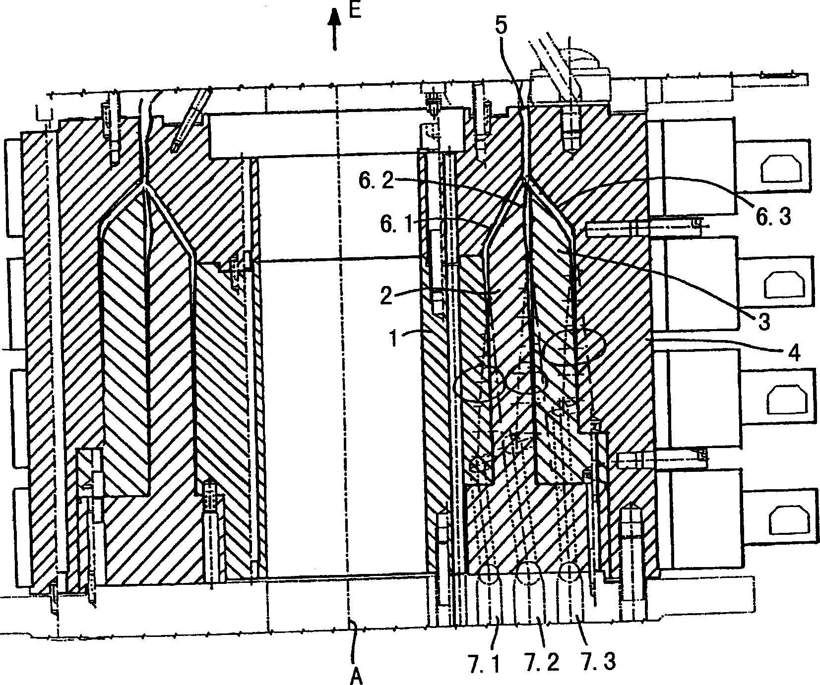
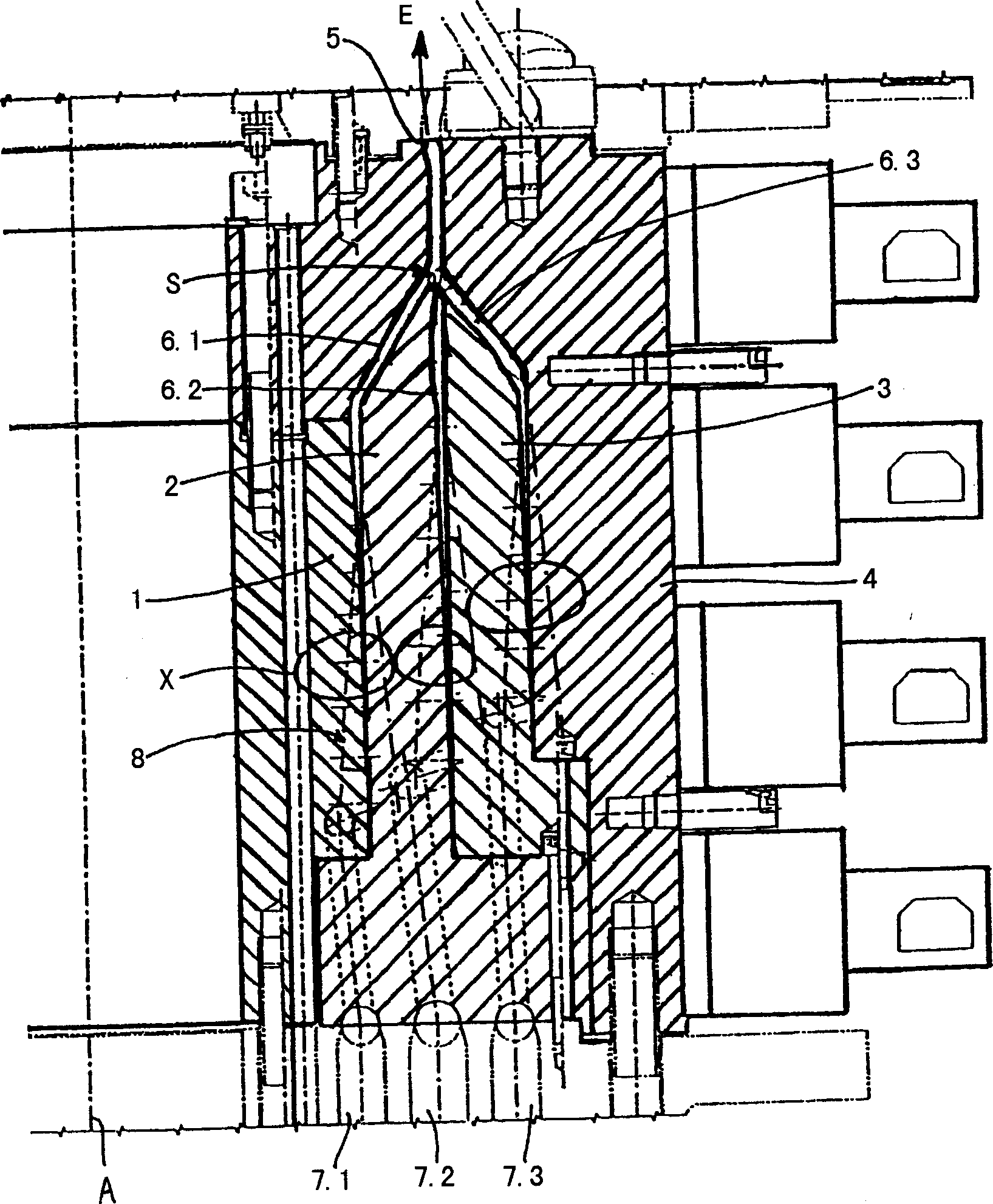
[0018] figure 1 A longitudinal section along the central axis A of a die for extruding a tubular molten tube from thermoplastic (for example for the manufacture of pressed foils) is shown in . The mold is a multilayer mold, here a three-layer mold, and comprises, in a known manner, an inner core 1 , the outer side of which is surrounded by an inner distribution part 2 while retaining the first melt channel 6 . Next, an outer distribution part 3 is arranged outside the inner distribution part, wherein a second melt channel 6.2 is formed between the inner distribution part 2 and the outer distribution part 3 . Finally, the outer side of the mold is closed by the outer casing 4 , wherein a melt channel 6 . 3 is formed between the outer distribution part 3 and the outer casing 4 .

[0019] The melt channels 6.1, 6.2, 6.3 supply the thermoplastic melt from the underside of the mould, via respective inlets 7.1, 7.2, 7.3, to extrusion devices not shown, and their melt channels 6.1, ...


PUM


Abstract

A tool for extruding a pipe-shaped melt strand of thermoplastic material, having a ring-shaped outlet nozzle and at least one melt conduit leading from an associated inlet opening to the outlet nozzle, which extends concentrically with respect to the center axis of the tool and into whose peripheral wall spirally turning helices are cut and form a helical manifold extending in the outlet direction of the melt strand. The helices are cut into the inner peripheral wall and into the outer peripheral wall of the at least one melt conduit.

Description

technical field [0001] The present invention relates to a mold for extruding a tubular molten pipe from thermoplastics, comprising a tubular outlet nozzle and at least one molten liquid channel that makes the corresponding inlet lead to the outlet nozzle and is distributed centrally with the central axis of the mould, defined in their On the wall, helical spiral grooves are formed by spiral distributors (wendelverteilers) extending in the output direction of the melting tube. Background technique [0002] Dies of this type are known, for example, from DE 44 07 060 A1 and DE 39 25 042 A1. [0003] One of the biggest problems with dies for extruding tubular melt tubes of thermoplastics, for example for the manufacture of press foils, is to achieve a uniform distribution of the melt coming out of the melt inlet in the die and subsequent melting through a uniform distribution over its circumference. The tube exits the tubular delivery nozzle. If logistics fluctuations occur, t...

Claims


Application Information

Patent Timeline
IPC IPC(8): B29C47/06B29C48/335B29C48/34
CPCB29L2023/001B29C47/065B29C47/0026B29C47/268B29C47/705B29C47/28B29C47/0023B29C47/26B29C48/05B29C48/09B29C48/10B29C48/21B29C48/335B29C48/338B29C48/34B29C48/705
Inventor P·施托梅尔
Owner REIFENHAEUSER MASCH DE
Why Eureka
Try Eureka