
Wiper blade for vehicle

A wiper, wiper arm technology, used in vehicle maintenance, vehicle cleaning, transportation and packaging, etc.

Inactive Publication Date: 2004-05-19
ROBERT BOSCH GMBH
View PDF3 Cites 2 Cited by
  • Summary
  • Abstract
  • Description
  • Claims
  • Application Information

AI Technical Summary

Problems solved by technology

Here inevitably a malfunction or a failure

Method used


Image

  • Wiper blade for vehicle
  • Wiper blade for vehicle
  • Wiper blade for vehicle

Examples


Embodiment Construction

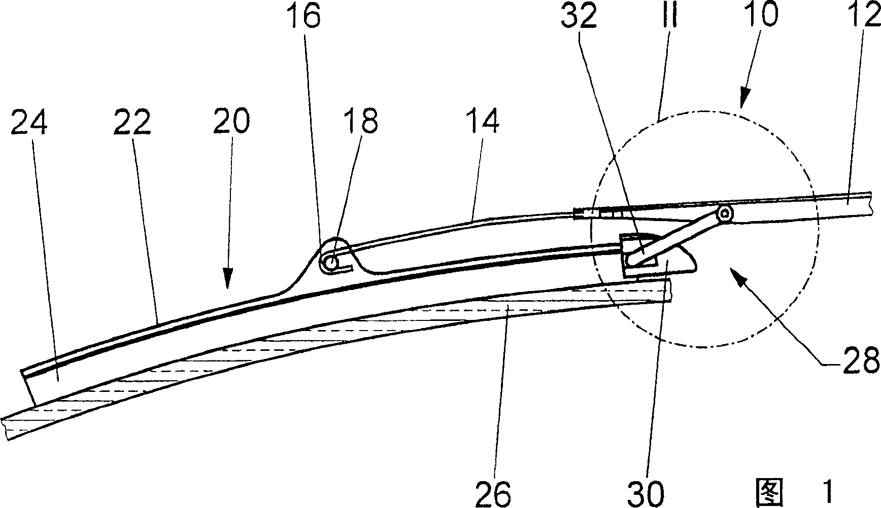
[0029] 1 shows a hinge 12 of a wiper arm 10 and a wiper rod 14, the hook-shaped end 16 of the wiper rod surrounds the hinge pin 18 of a wiper blade 20 and thus makes the wiper blade 20 It is hingedly connected with the wiper arm 10. The wiper blade 20 has a wiper strip strut 22 and a wiper strip 24 . This wiper strip bears against the window pane 26 .

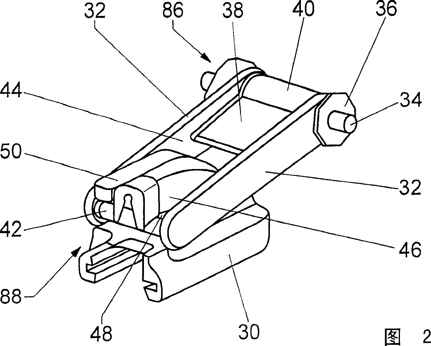
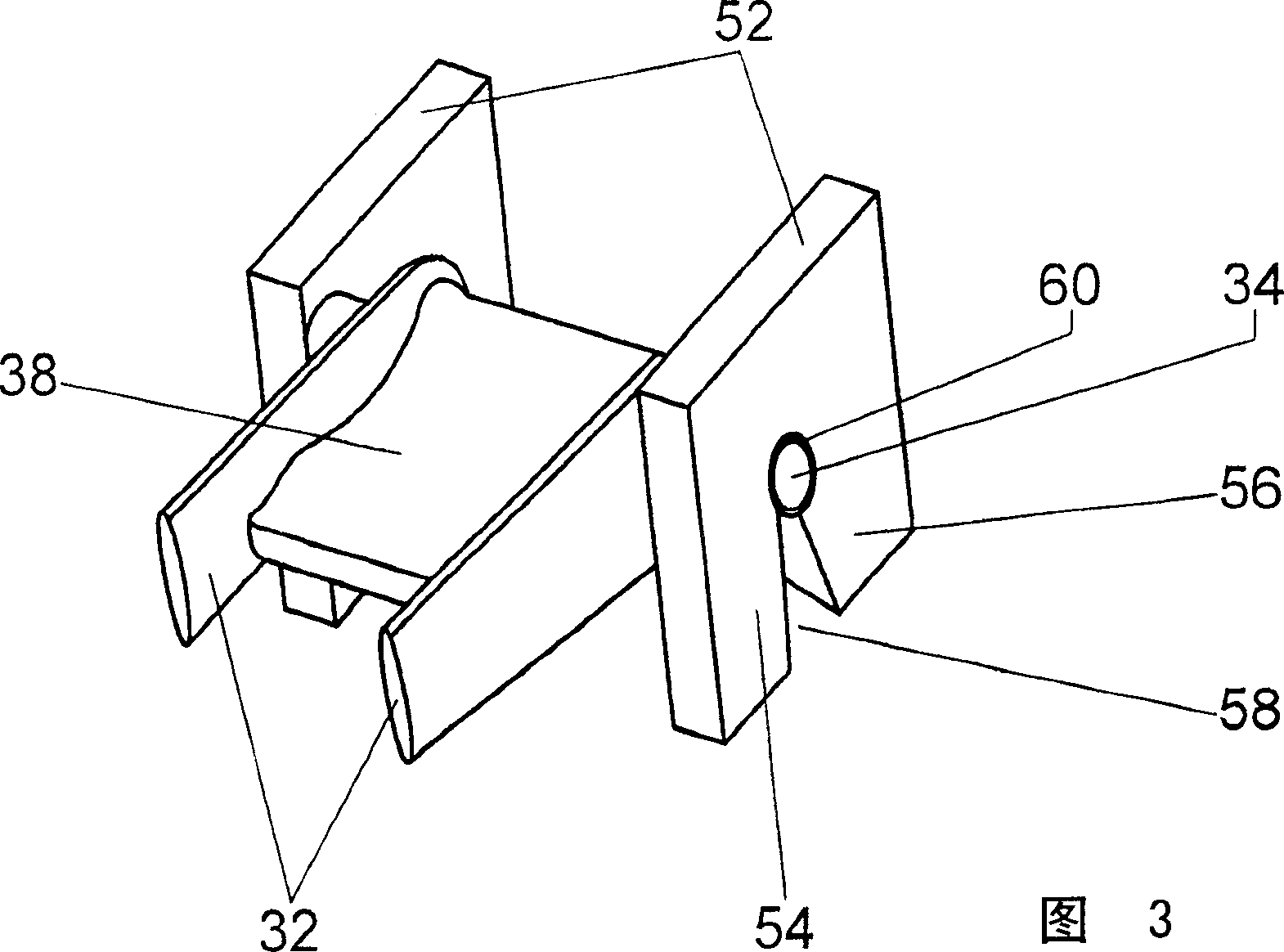
[0030] Between the wiper blade 20 and the joint 12 of the wiper arm 10 there is a device 28 ( FIG. 2 ) for laterally guiding the wiper blade 20 with two connecting rods 32 arranged in parallel. The connecting rod 32 is rotatably mounted at its ends in swivel bearings 86 and 88 . On the side of the wiper arm 10 , the pivot bearing 86 has a pivot shaft 34 which is fixedly connected to the connecting rod 32 and consists of two lateral pins. The axis of rotation 34 can also pass integrally through the sleeve part 40 of the device 28 . It is either fixedly connected to the connecting rod 32 and the sleeve part 40 and is pivotabl...


PUM


Abstract

The invention relates to a wiper blade (20) which comprises a wiper strip carrier (22) and a wiper strip (24) and which is guided laterally by a device (28) with a guide rod (32,74) in relation to the wiper arm (10). One end of the guide rod (32,74) is pivotally fixed to a hinged part (12) of the wiper arm (10) in an approximately perpendicular manner with respect to a windscreen (26) and the lateral guide surfaces of the guide rod (32,74) are adjacent to a part of the wiper blade (20). According to the invention, a pivoting bearing (86, 88) is arranged on both ends of the guide rod (32,74), enabling movement in the longitudinal direction of the wiper arm (10) or wiper blade. (20).

Description

technical field [0001] The invention relates to a wiper blade according to the preamble of claim 1 . Background technique [0002] The known windshield wiper has a wiper arm which is formed from a fastening part and an articulated part with a wiper rod which is articulated thereto. The wiper rod can be firmly connected to the hinge part as a special component or directly integrally formed on the hinge part. A wiper blade with a wiper strip strut and a wiper strip is articulated to the wiper lever. Usually the wiper slat struts consist of a support bow system with a central bow, and sometimes with lower bows, such as a middle bow and / or claw bows, which clamp a wiper slat Hold on. Such windshield wipers are known, for example, from DE 37 44 237 A1. [0003] Also known from DE 197 38 232 A1 is a hingeless support element made of elastic high-strength plastic, which clamps the wiper strip and has a bend in the unloaded state. This curved design It should be ensured that wh...

Claims


Application Information

Patent Timeline
Patent Type & Authority Applications(China)
IPC IPC(8): B60S1/42B60S1/00B60S1/32B60S1/38
CPCB60S2001/3822B60S1/3497B60S1/38B60S1/3894B60S1/32B60S1/40
Inventor S·迈尔
Owner ROBERT BOSCH GMBH
Learn More