Connecting mechanism of tape drive wheel electric machine for tape recorder

A tape recording and electrical connection technology, applied in the direction of record carrier drive mechanism, record carrier structural parts, data recording, etc.

Inactive Publication Date: 2004-05-19
SAMSUNG ELECTRONICS CO LTD
View PDF0 Cites 2 Cited by
  • Summary
  • Abstract
  • Description
  • Claims
  • Application Information

AI Technical Summary

Problems solved by technology

[0006] Then, the reel motor connection structure of the conventional tape recorder has a limit in the amount by which the overall height of the tape recorder can be reduced, because the connector bracket 21 and the connector 41 respectively provided on the master PCB 20 and the slave PC...

Method used


Image

  • Connecting mechanism of tape drive wheel electric machine for tape recorder
  • Connecting mechanism of tape drive wheel electric machine for tape recorder
  • Connecting mechanism of tape drive wheel electric machine for tape recorder

Examples


Embodiment Construction

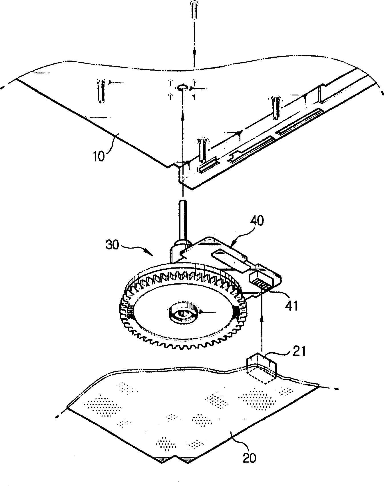
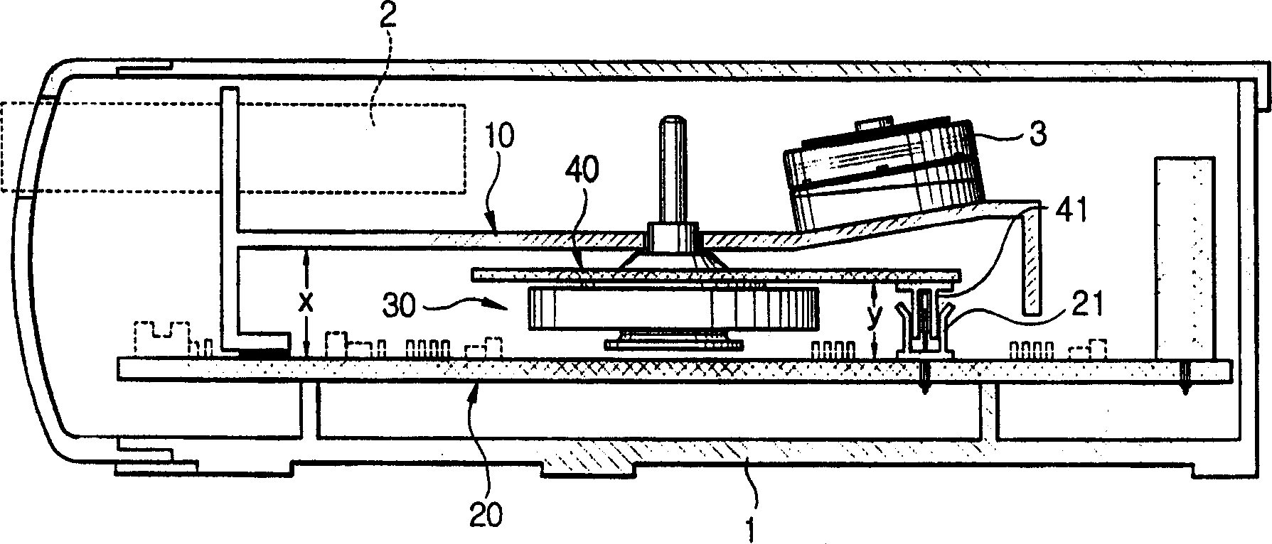
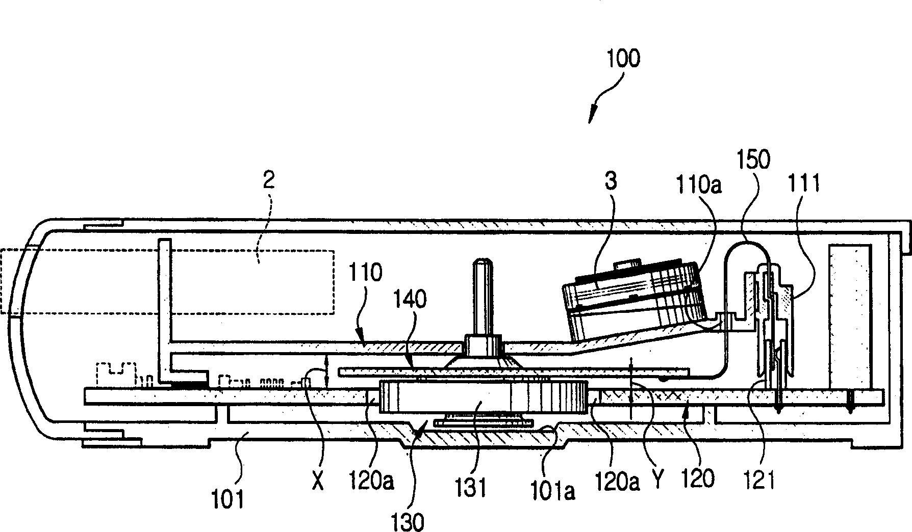
[0019] refer to Figures 3 to 5 , the magnetic tape recorder 100 having the connection structure of the reel motor according to an embodiment of the present invention includes a first connector 121 electrically connected to the main PCB 120; The second connector 111 on the connector 121; the support hole 110a formed in the main base 110; and the cable 150 penetratingly supported in the support hole 110a for electrically connecting the slave PCB 140 of the reel motor 130 to on the second connector 111. Also, the main PCB 120 has a hole 120a formed therein, and the reel motor 130 is embedded relative to the main PCB 120, and the main body 131 of the reel motor 130 is placed in the hole 120a so that the distance X between the main substrate 110 and the main PCB 120 decreases. Small. In this example, reference numerals 101, 2, and 3 denote a case, a cassette, and a head drum, respectively.

[0020] According to the above structure, the distance X between the main substrate 110 ...


PUM


Abstract

A capstan motor connection structure of a tape recorder comprising a first connector disposed at a main printed circuit board (PCB) to be electrically connected to the main PCB , a second connector disposed at an end of the main base corresponding to the first connector to be electrically connected to the first connector , and a cable penetratingly supported in a supporting hole formed in the main base , for electrically connecting the sub PCB of the capstan motor to the second connector . The capstan motor is arranged with its body being placed in a hole formed in the main PCB , to thus reduce a distance between the main base and the main PCB . Accordingly, the overall height of the tape recorder can be reduced.

Description

technical field [0001] The present invention relates to a tape recorder, such as a video recorder (VCR), and more particularly to an arrangement for connecting a master printed circuit board (PCB) of the tape recorder to a slave PCB on a deck motor. Background technique [0002] A tape recorder such as a VCR is provided with various types of drive motors such as a head drum motor, a tape loading motor, a reel motor, and a deck motor. [0003] figure 1 is a deck motor 30 to be mounted on a main base 10 of a deck of a magnetic tape recorder is shown. The deck motor 30 arranged to run the video tape at a constant speed includes a slave PCB 40 with a speed control circuit as it makes the deck motor 30 rotate precisely. The deck motor 30 is electrically connected to the main PCB 20 of the tape recorder through a connector 41 mounted on the slave PCB. [0004] like figure 2 The connection structure of the belt reel motor of the traditional magnetic tape recorder shown is that...

Claims


Application Information

Patent Timeline
IPC IPC(8): G11B15/26G11B15/28G11B15/44G11B33/12
CPCG11B15/26G11B15/28G11B15/44G11B33/121G11B33/122
Inventor 薛咏润李桓承
Owner SAMSUNG ELECTRONICS CO LTD
Why Eureka
Try Eureka