Electro-optical deivce, matrix base plate and electronic machine
一种电光装置、矩阵的技术
- Summary
- Abstract
- Description
- Claims
- Application Information
AI Technical Summary
Problems solved by technology
Method used
Image

Examples
Embodiment 1
[0029] Hereinafter, this embodiment will be described with reference to the drawings.
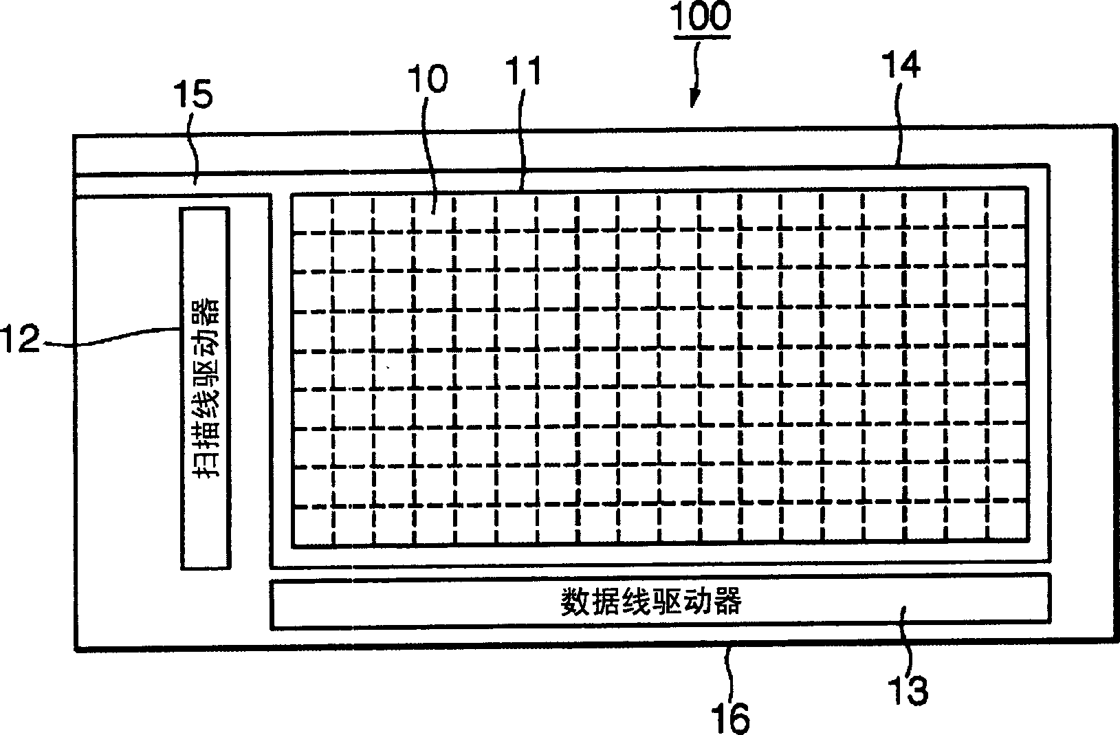
[0030] figure 1 It is an overall configuration diagram of the active matrix organic EL display panel 100 of this embodiment. As shown in the figure, the display panel 100 is composed of a display area 11 provided with a plurality of pixels 10 arranged in a matrix of N rows and M columns on a substrate, and output to a scanning line connected to a group of pixels 10 arranged in the row direction. A scanning line driver 12 for scanning signals and a data line driver 13 for supplying data signals and power supply voltages to data lines and power supply lines connected to a group of pixels 10 arranged in the column direction are configured. On each pixel 10, an organic EL element emitting light in three primary colors of RGB is formed. A cathode 14 serving as a common electrode is formed on the entire surface of the display region 11 and is connected to an external circuit through a cathode l...
Embodiment 2
[0038] Figure 4 It is an explanatory diagram of the wiring layout of the embodiment.
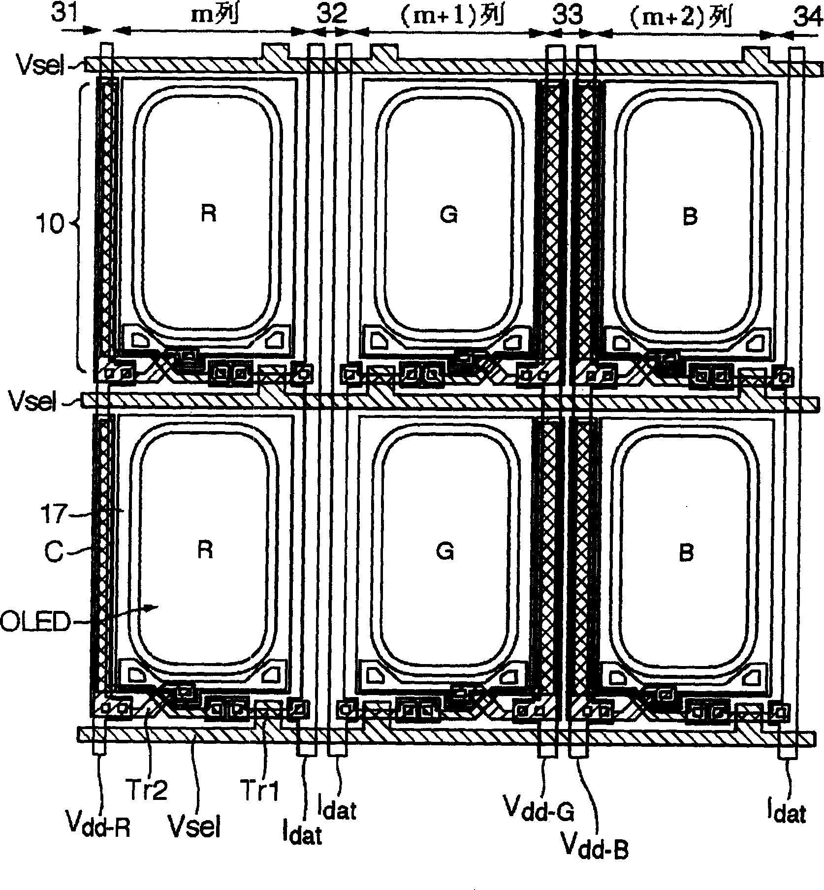
[0039] In the present embodiment, a layout diagram for specifying the layout of wiring forming regions formed along the row direction of pixels is hypothetically provided, and a specific wiring forming region is focused on among a plurality of wiring forming regions. When the center is virtually returned to the layout diagram, wiring formation regions having the same type of wiring combination are overlapped. Three power supply lines V dd-G , V dd-R and V dd-B Arranged in the row direction as a group, the two scanning lines V sel As a group is laid out in the row direction. The basic form of the row direction wiring layout is to connect the three power lines V dd-G , V dd-R and V dd-B and two scan lines V sel They are respectively regarded as a group of layouts, and this basic form is laid out periodically and repeatedly. Therefore, the wiring layout of the wiring formation region...
Embodiment 3
[0043] Figure 5 It is an explanatory diagram of the wiring layout of Embodiment 3 of the present invention.
[0044] In this embodiment, a layout diagram specifying the arrangement and layout of wiring formation regions formed along the row direction of pixels is hypothetically provided, and a specific wiring formation region is focused on among a plurality of wiring formation regions. When the above-mentioned layout diagram is virtually returned to the center, wiring formation regions having the same type of wiring combination are overlapped and constituted. Three power supply lines V dd-G , V dd-R and V dd-B Arranged in the row direction as a group, the two power supply lines V sel As a group is laid out in the row direction. The basic form of the row direction wiring layout is to connect the three power lines V dd-G , V dd-R and V dd-B and two scan lines V sel They are respectively regarded as a group of layouts, and this basic form is repeatedly laid out periodic...
PUM
 Abstract
Description
Claims
Application Information
 - Generate Ideas
- Intellectual Property
- Life Sciences
- Materials
- Tech Scout
- Unparalleled Data Quality
- Higher Quality Content
- 60% Fewer Hallucinations
Browse by: Latest US Patents, China's latest patents, Technical Efficacy Thesaurus, Application Domain, Technology Topic, Popular Technical Reports.
© 2025 PatSnap. All rights reserved.Legal|Privacy policy|Modern Slavery Act Transparency Statement|Sitemap|About US| Contact US: help@patsnap.com