Heating device

一种加热装置、传动装置的技术,应用在发热装置、照明和加热设备、加热/冷却设备等方向,能够解决费事等问题,达到控制简化、简化外壳设计、小惯性的效果

Inactive Publication Date: 2004-05-19
BORGWARNER INC
View PDF6 Cites 5 Cited by
  • Summary
  • Abstract
  • Description
  • Claims
  • Application Information

AI Technical Summary

Problems solved by technology

[0005] Although the European patent EP-0 826 530 A2 has already proposed to combine the delivery device of the temperature-controlled fluid with the heating device working with shear force, but in this respect these two units are formed on separate components in themselves, they only act mutually. flange connections, where the controlled circulation of the temperature-regulating fluid from one component to another is as complex as the circulation of viscous liquids

Method used


Image

  • Heating device
  • Heating device

Examples


Embodiment Construction

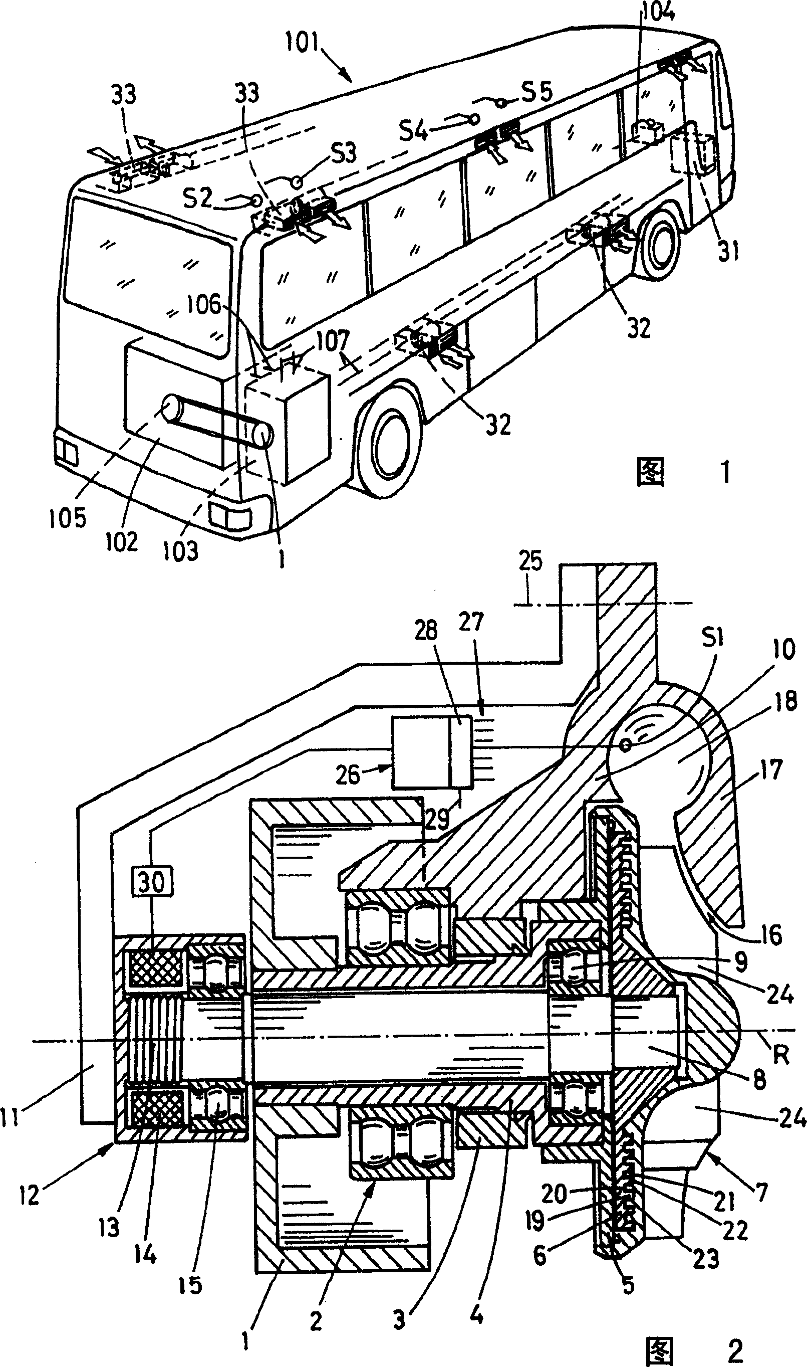
[0017] FIG. 1 shows a motor vehicle 101 with a drive engine 102 like a gasoline or diesel engine at the rear of the vehicle. The engine 102 drives the transmission wheel 1 of the temperature control unit 103 through a belt pulley 105 that is generally a V-belt pulley and may also be a sprocket if necessary. This temperature control unit has a cooling device that is known per se and therefore will not be described in detail here. A heating device according to the invention. It will be appreciated that the present invention is not limited to a certain type of automobile, but may also be used in cars, trucks and the like. It has already been mentioned above that the invention can also be used for heating stationary rooms.

[0018] The temperature control device 103 has a line 106 for circulating the cooling of the engine 102 and a line 107 for circulating a liquid such as water for air-conditioning the interior of the vehicle 101 . It is understood that the heating device accor...


PUM


Abstract

The chamber (23) containing the viscous fluid being sheared, is constructed directly in a cavity of the impeller rotor (7)

Description

technical field [0001] The invention relates to a heating device for a temperature-controlled fluid conveyed by means of a conveying rotor. Within the scope of the present invention, such fluids may generally be of a liquid form, and optionally also of a gaseous type. Fields of application of such heaters can also be used for particularly different purposes, like room temperature control, heating of cooling liquids for internal combustion engines, etc. [0002] The delivery rotor is mounted on a shaft which is rotated by a drive device, wherein the heating device generates heat for release to the temperature control fluid by shear forces in the chamber containing the viscous liquid by means of the rotating shear structure. Background technique [0003] Heating devices that work with shear forces are disclosed in very different embodiments. For example US Patents 5,778,843; 6,047,896 and 6,138,920. In this case, the latter introduces a rather complex control of the heating...

Claims


Application Information

Patent Timeline
Patent Type & Authority Applications(China)
IPC IPC(8): F01P3/20B60H1/02B60H1/03B60H1/14F01P5/10F24J3/00
CPCB60H1/038B60H1/14F24J3/003B60H2001/146F24V40/00B60H1/02
Inventor C·蒂利
Owner BORGWARNER INC
Why Eureka
Try Eureka