Control box device for sewing mechine

A sewing machine and control box technology, applied in the direction of sewing machine control devices, sewing machine components, sewing machine housings, etc., can solve problems such as frame P26 deformation, and achieve the effects of avoiding negative effects, improving cooling effect, and reliable ventilation

Inactive Publication Date: 2004-05-12
JUKI CORP
View PDF0 Cites 7 Cited by
  • Summary
  • Abstract
  • Description
  • Claims
  • Application Information

AI Technical Summary

Problems solved by technology

[0014] However, in the conventional control box P20, since the frame P26 is installed horizontally, every time the pedal is stepped, a load is applied to the end of the frame P26, and there is a torsional load on the frame P26 as a whole. Circumstances that cause rack P26 to deform

Method used


Image

  • Control box device for sewing mechine
  • Control box device for sewing mechine
  • Control box device for sewing mechine

Examples


no. 1 Embodiment

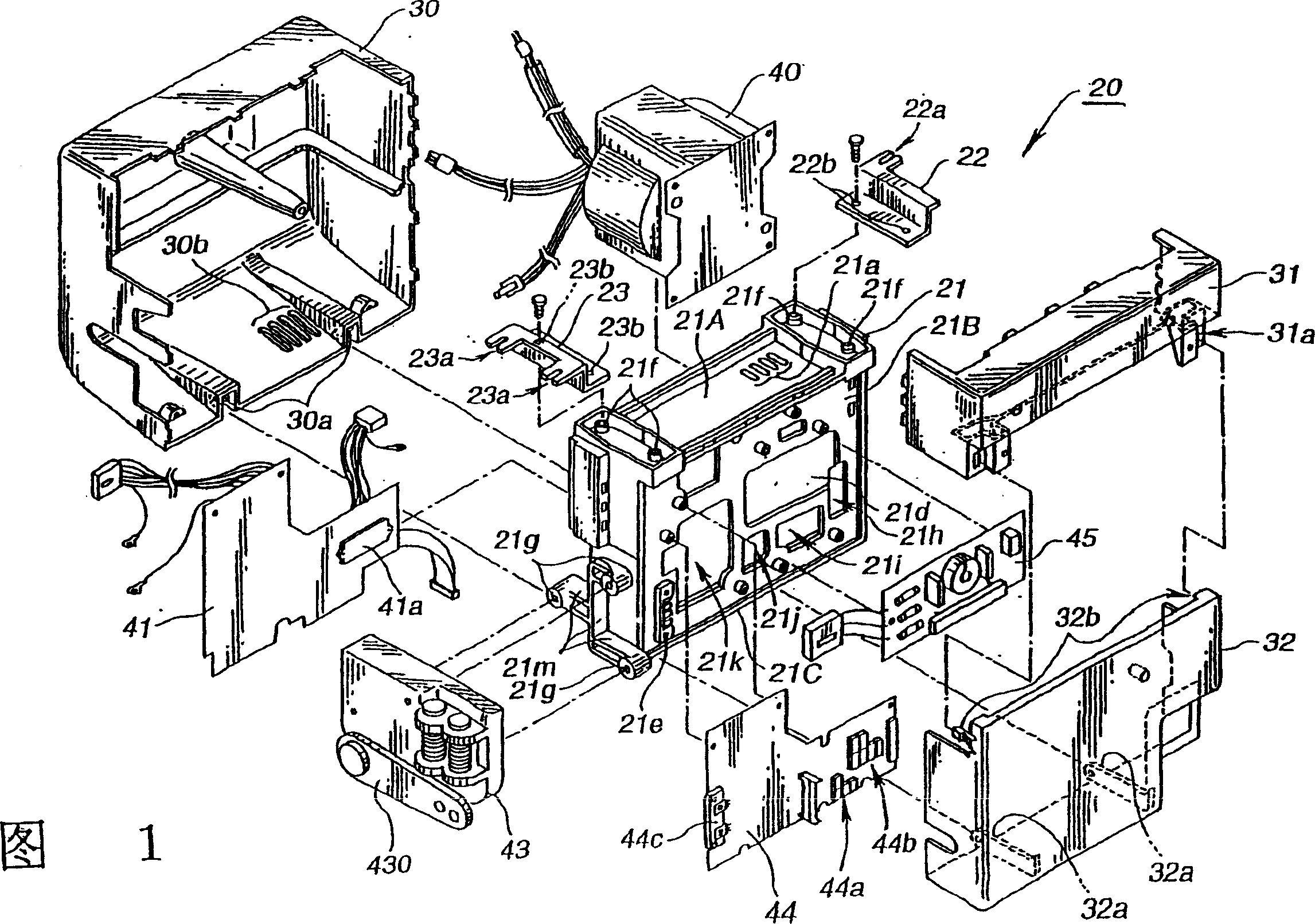
[0054] The control box 20 of this embodiment is composed of a frame 21 as a main frame on which several electrical components are installed; a first cover 30 covering the outside, a second cover 31 and a third cover 32, and mounting accessories 22 and 23 as mounting components. .

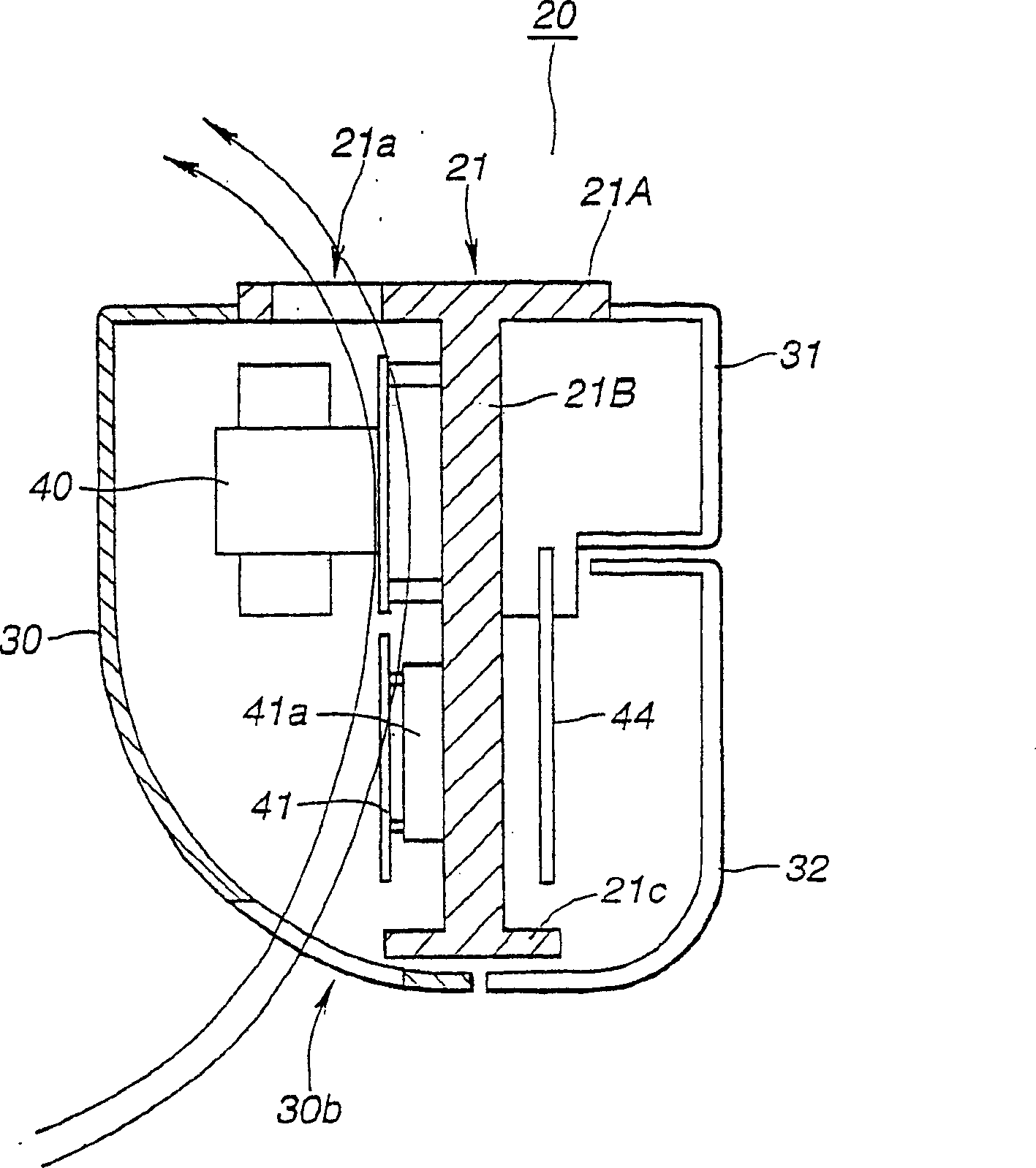
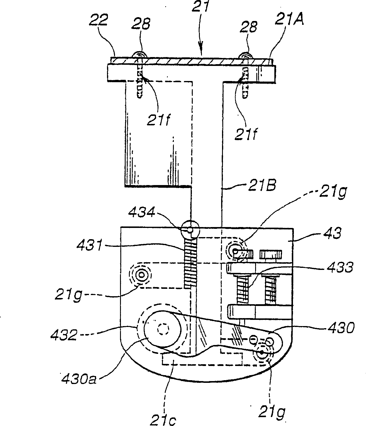
[0055] The frame 21 is made of metal, such as integrally formed with aluminum die-casting parts, and made as figure 2 The section shown is T-shaped, and consists of a plate-shaped main frame part (frame member) 21B extending in the vertical direction, an upper frame part 21A and a lower frame part 21C arranged horizontally above and below the main frame part 21B, etc. constitute. The upper frame part 21A is not only used as a reinforcing member because of the high bending stress of the main frame part 21B, but also serves as a base frame for installing the control box 20 at the installation position, and forms an installation fitting for fixing the control box 20 for installation. 22, 23 screw ho...

no. 2 Embodiment

[0082] Figure 8 The sewing machine control box 200 of the second embodiment is shown.

[0083] In the control box 200 of this embodiment, the frame portion 153 and the lower cover portion 150 are integrally formed, and other configurations are basically the same as those of the first embodiment.

[0084] The frame body 152 is made into a Y-shaped section structure, and the upper end 150D of the lower cover portion 150 of the upper structure hangs around the sewing machine installation hole 102A of the sewing machine table 102 to support it. Furthermore, there is provided a frame portion 153 hanging downward from the center portion in the front-rear direction of the lower end surface (constituting the upper frame portion) 150B of the lower cover portion 150 .

[0085] The first cover 160 covering the rear of the frame portion 153, the second cover 161 covering the front and upper side of the frame portion 153, and the third cover 162 covering the front of the frame portion 15...


PUM


Abstract

To make a control box compact and to improve cooling efficiency of a heating part by providing a plate-like frame member vertically extending, and installing an electric part on both surfaces of the member in the control box arranged under a sewing machine table and housing a sewing machine control electric part. A frame 21 of a control box 20 of a sewing machine is made of metal, and is constituted in a cross-sectional view T shape out of the plate- like main frame part 21B extending in the vertical direction and the upper/lower frame parts 21A, 21C horizontally arranged above and below it. An electric part such as a motor drive circuit containing an inverter circuit for driving a power transformer 40 and a sewing machine motor is installed in the main frame part 21B. The opening parts 21h to 21k are formed in the main frame part 21 to improve weight reduction and gas permeability, the projecting parts 21d and 21e are arranged to receive heat radiation by contacting with a heating part containing the power transformer 40, and drive elements 41a, 44c are contacted with the respective projecting parts 21d, 21e.

Description

[0001] The present invention is a divisional application of the patent application whose filing date is June 12, 1999, whose application number is "03107747.1", and whose title is "control box of sewing machine". technical field [0002] The invention relates to a sewing machine control box arranged under the sewing machine table in the technical field of industrial sewing machines for accommodating electrical components used for sewing machine control. Background technique [0003] On an industrial sewing machine, a sewing machine motor for driving the sewing machine is provided under the sewing machine table, and a control box is installed on the lower side thereof. [0004] also, Figure 10 and Figure 11 An industrial sewing machine is shown in which the sewing machine motor is installed on the head side of the sewing machine as the size of the sewing machine motor is reduced. Among them, P17 represents the sewing machine head, P18 represents the sewing machine motor, P...

Claims


Application Information

Patent Timeline
Patent Type & Authority Applications(China)
IPC IPC(8): D05B69/18D05B69/00D05B71/00D05B73/04
Inventor 田内司和田稔小滝浩志村井健二洼田义彦
Owner JUKI CORP
Why Eureka
Try Eureka