
Bushing temp controller

A technology of temperature control device and shaft sleeve, which is applied in the direction of temperature control by electric means, manufacturing tools, glass manufacturing equipment, etc. It can solve problems such as instability, inability to adjust the current flow of shunt circuits, and complicated temperature adjustment operations, and achieve spinning The effect of high efficiency of wire operation

Inactive Publication Date: 2004-05-05
NITTO BOSEIKI CO LTD
View PDF2 Cites 1 Cited by
  • Summary
  • Abstract
  • Description
  • Claims
  • Application Information

AI Technical Summary

Problems solved by technology

At this time, even if the current supply amount becomes zero, and it is necessary to lower the temperature, it is necessary to adjust the current supply amount of the main first power transformer or adjust the lower part of the sleeve for cooling drawn from a plurality of holes. Cooling fins that melt glass, so temperature adjustment becomes very troublesome
[0011] In the temperature control device described in JP-A-11-327661, since the amount of current shunted by the shunt circuit cannot be adjusted, even fine temperature control will become a cause of instability (hunting), and it is possible Generate Tex changes

Method used


Image

  • Bushing temp controller
  • Bushing temp controller
  • Bushing temp controller

Examples


Embodiment Construction

[0021] Hereinafter, embodiments of the present invention will be described with reference to the drawings. In addition, the same code|symbol is attached|subjected to the same element in each figure, and overlapping description is abbreviate|omitted. In addition, the dimensional ratios in the drawings do not necessarily match the descriptions.

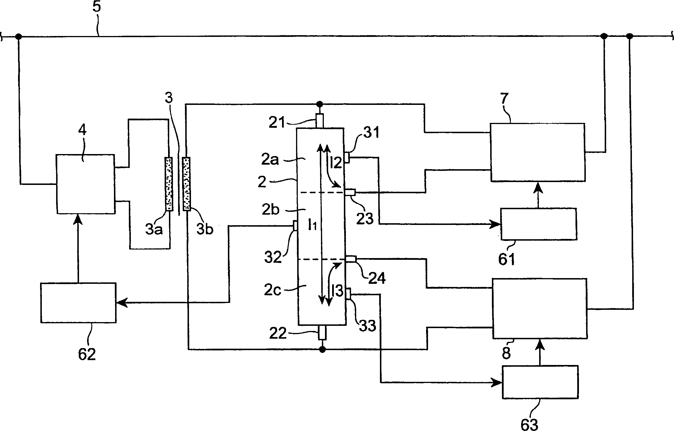
[0022] figure 1 It is a schematic diagram showing the configuration of the sleeve temperature control device according to the present embodiment.

[0023] As shown in this figure, the sleeve temperature control device 1 according to this embodiment is a device for controlling the temperature of the sleeve 2, and controls the temperature of the sleeve 2 by passing a predetermined current through the sleeve 2 and adjusting the current flow amount. The temperature of the bushing 2 means. The bushing 2 is a container for storing molten glass, and the molten glass is flowed out from a plurality of holes (not shown) formed in the bottom to...


PUM


Abstract

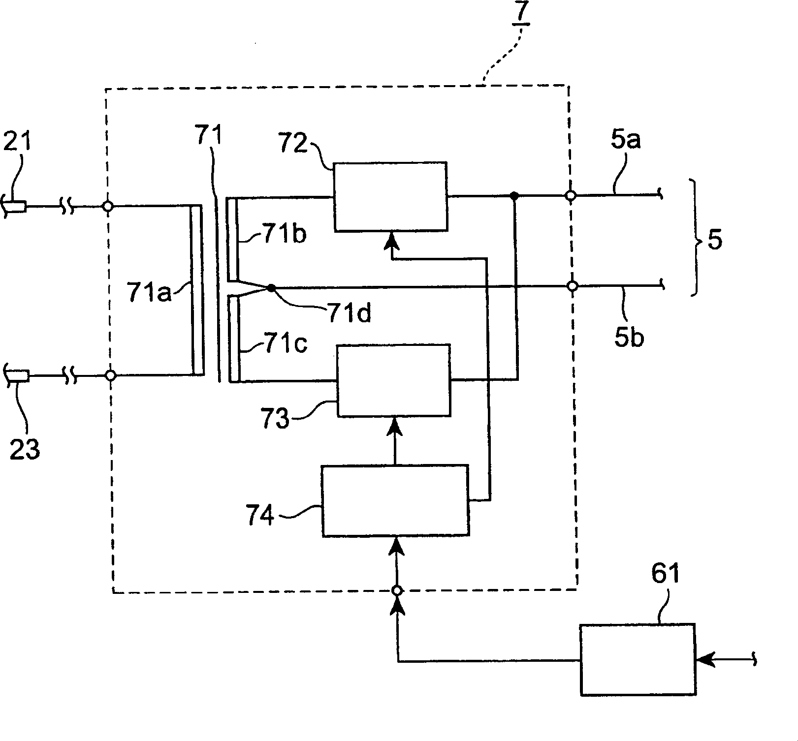
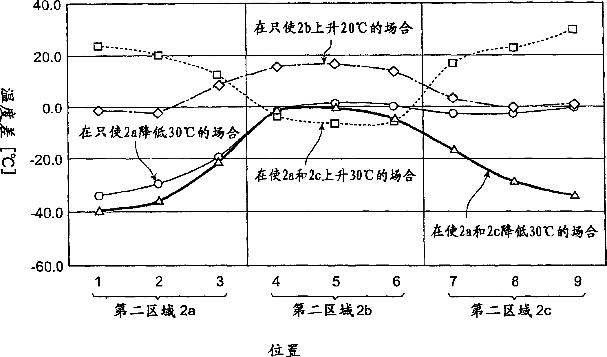
A bushing temperature controller includes a transformer 3 which supplies a main current 11 to the bushing 2 for accommodating molten glass, and regulation current supply units 7 and 8 which are adapted to supply regulation currents I2 and I3 either in phase with the main current I1 or in phase inverted to the main current I1 to a portion of a region to which the transformer 3 applies the current. Thus, the temperature control of partial regions 2a and 2c in the region to which the current is applied can be performed in a wide temperature range.

Description

technical field [0001] The present invention relates to a sleeve temperature control device for controlling the temperature of a sleeve used for spinning glass fibers. Background technique [0002] Generally, glass fibers are spun by forming a plurality of holes in the bottom of a sleeve that accommodates molten glass, letting glass fibers flow out from these holes, and bundling and winding up a plurality of fibers. At this time, in order to obtain uniform glass fibers, the sleeve must be heated to a uniform temperature. This heating is performed by passing an electric current through the bushing. [0003] The conventional temperature control of the bushing is carried out by converting the thermoelectromotive force of the thermocouple arranged in the center of the bushing into temperature, and passing a predetermined current through the bushing to keep the temperature constant. The temperature is kept constant. [0004] However, the current density tends to be higher at b...

Claims


Application Information

Patent Timeline
Patent Type & Authority Applications(China)
IPC IPC(8): C03B37/092
CPCC03B37/092
Inventor 安斋岩八卷昇
Owner NITTO BOSEIKI CO LTD
Learn More