Eureka AIR delivers breakthrough ideas for toughest innovation challenges, trusted by R&D personnel around the world.

Waste toner recovering apparatus and image forming apparatus

A technology of waste toner and recycling device, which is applied in the fields of electric recording technology using charge pattern, equipment for electric recording technology using charge pattern, and electrography, and can solve the problem of waste toner collapse, toner overflow, and difficulty in storage To prevent the toner from overflowing or not being filled, improve the accumulation limit, and prolong the replacement cycle

Inactive Publication Date: 2004-05-05
RICOH KK
View PDF0 Cites 14 Cited by
  • Summary
  • Abstract
  • Description
  • Claims
  • Application Information

AI Technical Summary

Problems solved by technology

[0007] The former filling method produces a swinging sound and requires a swinging mechanism
In addition, since the waste toner recovery container swings, the waste toner recovery container to be replaced and discarded must have a sensor for detecting whether it is full, resulting in an increase in the cost of the waste toner recovery container, and the occurrence of joint connectors during replacement. homework
[0008] The latter filling method can collapse the waste toner accumulated in the waste toner recovery container. However, since the shape of the recovery container is not considered, the accumulated waste toner cannot be fully recovered when the shape of the waste toner recovery container is complicated. The toner collapses, and as a result, the waste toner tends to solidify, and there is a danger of the toner overflowing from the container
That is, with the miniaturization and high-performance of image forming apparatuses, the internal space of the device body becomes narrower, and if the waste toner recovery container is not designed according to the shape of the remaining space in the body, it is difficult to accommodate it in the device body.
Therefore, the shape of the waste toner recovery container is made to match the shape of the remaining space in the main body, but in this case, the shape becomes a special shape, and there is a place in the container where the waste toner tends to stagnate.

Method used


Image

  • Waste toner recovering apparatus and image forming apparatus
  • Waste toner recovering apparatus and image forming apparatus
  • Waste toner recovering apparatus and image forming apparatus

Examples


Embodiment Construction

[0057] Embodiments of the present invention will be described in detail below with reference to the accompanying drawings.

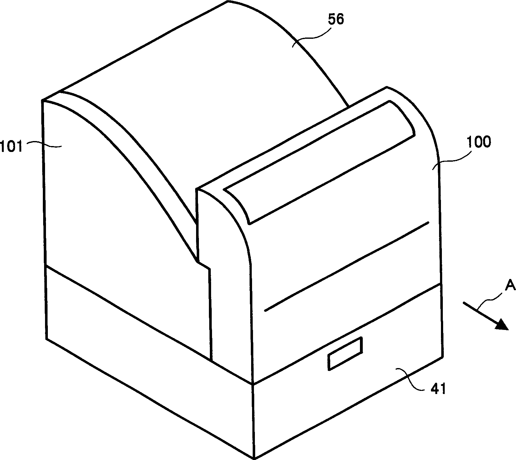
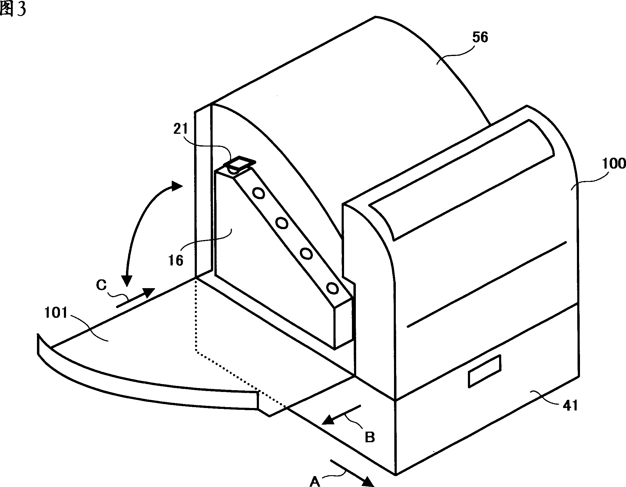
[0058] figure 1 Indicates a color printer as an image forming apparatus. Such as figure 1 As shown, the color printer is equipped with a paper feeding cassette 41 serving as a paper feeding section at the lower part of the device body for storing transfer paper P as a recording material. The transfer paper P in the cassette 41 is conveyed into the apparatus main body 100 by a paper feed roller 43 and a transport roller 44 provided near the paper feed cassette 41 . In the transfer paper conveying path between the conveying roller 44 and the secondary transfer unit 37 , a registration roller 45 is arranged to control the delivery timing of the transfer paper P to the secondary transfer unit 37 .

[0059] Inside the device body 100, there are:

[0060] The imaging cartridges 10Y, 10C, 10M, and 10K respectively form yellow, cyan, magenta, and black toner...


PUM


Abstract

A waste toner collecting device includes a container detachably set in an image forming apparatus and a waster toner transport device to transport waste toner in the container. The container has a shape as to fit into a free space of the image forming apparatus. The image forming apparatus also includes an image bearing member, and a cleaning device configured to collect a residual toner remaining on the image bearing member.

Description

technical field [0001] The present invention relates to a waste toner recovery device that uses, as waste toner, residual untransferred toner that is removed from an image carrier by a cleaning device, and an image forming apparatus provided with the recovery device. Recycle to the toner recovery container. Background technique [0002] In image forming apparatuses such as copiers, various printers, facsimile machines, and multifunction machines with the above functions, users themselves, as apparatus users, perform replacement or maintenance of consumables that were previously performed by maintenance personnel. In addition, with the downsizing and lowering of the price of the device, each component inside the device is also reduced to a minimum size. Therefore, until the end of the life of the device, the user needs to replace parts that cannot maintain quality, toner that becomes a developer, and waste toner that is used to store residues such as paper powder recovered f...

Claims


Application Information

Patent Timeline
Patent Type & Authority Applications(China)
IPC IPC(8): G03G15/01G03G21/10G03G21/12
CPCG03G21/105G03G21/12
Inventor 石井洋荒井裕司
Owner RICOH KK
Why Eureka
Eureka Blog
Learn More