
Operating apparatus and method for controlling piston booster

A piston compressor and compressor technology, which is applied in piston pump, pump control, mechanical equipment, etc., can solve problems such as nonlinearity and error, increase error, etc.

Inactive Publication Date: 2004-04-21
LG ELECTRONICS INC
View PDF0 Cites 3 Cited by
  • Summary
  • Abstract
  • Description
  • Claims
  • Application Information

AI Technical Summary

Problems solved by technology

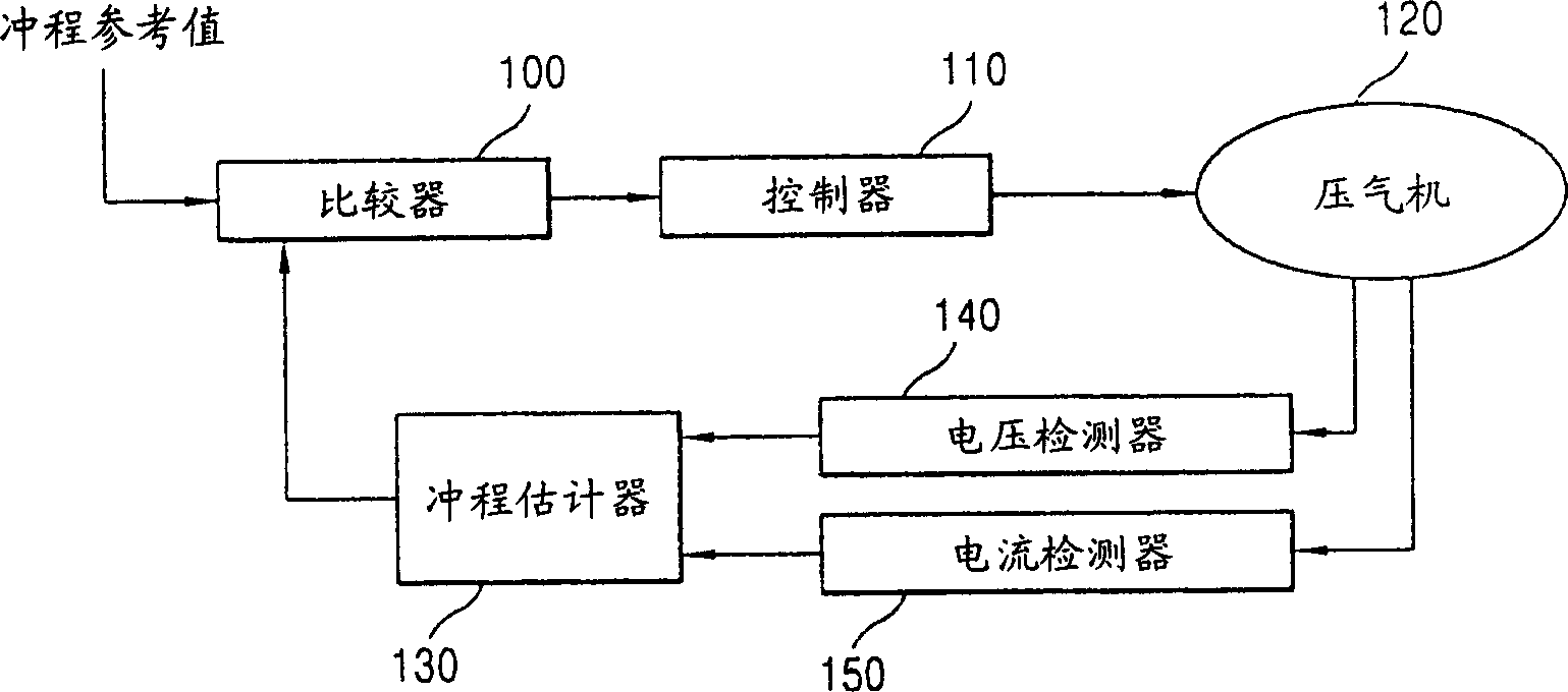
[0008] However, in the conventional operation control method of the piston compressor, since the stroke control is performed by estimating the stroke using all the engine parameters (engine constants, resistance, inductance, etc.), the increase due to the nonlinearity and error of the parameters Error in estimated stroke

Method used


Image

  • Operating apparatus and method for controlling piston booster
  • Operating apparatus and method for controlling piston booster
  • Operating apparatus and method for controlling piston booster

Examples


Embodiment Construction

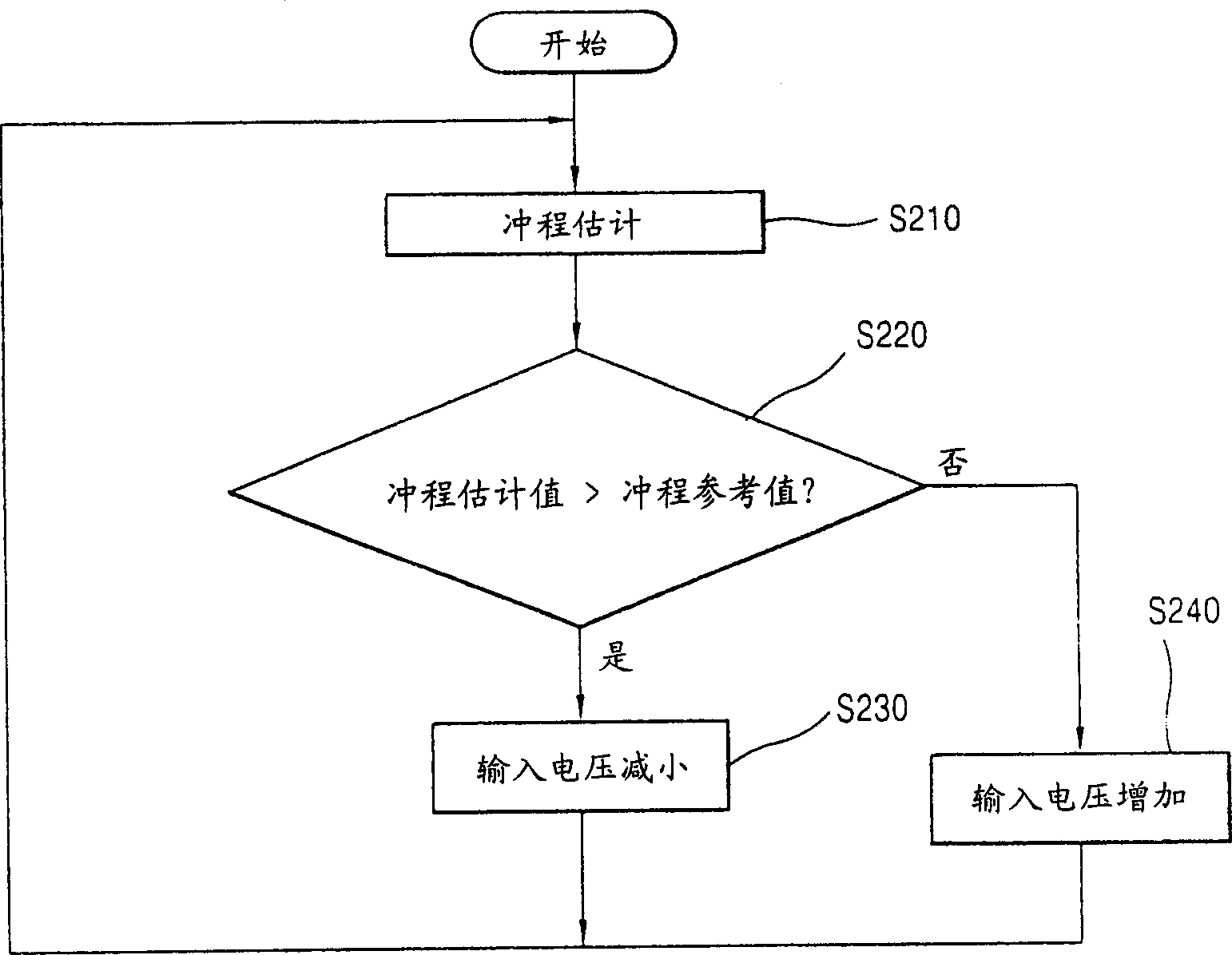
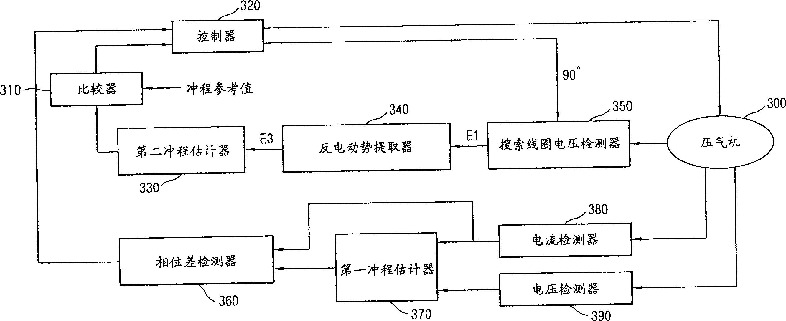
[0018] In the apparatus and method for controlling the operation of a piston compressor according to the present invention, after calculating the stroke estimated value by the same method as the conventional technique, in order to reduce the Inducing error, the phase of the calculated stroke is compared with the phase of the current supplied to the engine. When the phase difference is 90° in the comparison result, a new stroke is estimated, and when the phase difference is not 90° in the comparison result, the operating frequency supplied to the engine is changed, thereby improving the stroke control accuracy.

[0019] In more detail, after detecting the first stroke estimated value using the voltage and current supplied to the engine and the engine constant, the difference between the phase of the first stroke estimated value and the phase of the current supplied to the engine is calculated. Here, when the phase difference is 90°, the phase and magnitude of the voltage suppli...


PUM


Abstract

An apparatus and a method for controlling operation of a reciprocating compressor is capable of reducing a stroke estimation error by eliminating an error that occurs due to resistance and inductance of a compressor motor by estimating a stroke with a counter electromotive force induced by a searching coil. Furthermore, by leaving errors of inductance and resistance, among all motor parameters, out of consideration in stroke estimation, a stroke estimation error can be reduced.

Description

technical field [0001] The present invention relates to an apparatus and method for controlling the operation of a piston compressor, and more particularly to an apparatus and method for controlling the operation of a piston compressor capable of reducing a stroke estimation error by estimating the stroke using back electromotive force induced by a search coil , and to remove errors due to resistance and inductance in the compressor motor (hereinafter referred to as the motor). Background technique [0002] figure 1 is a block diagram illustrating an operation control device of a piston compressor according to the conventional art. Such as figure 1 As shown, the operation control device of the piston compressor includes: a current detector 150 for detecting the current supplied to the engine; a voltage detector 140 for detecting the voltage supplied to the engine; a stroke estimator 130 for detecting The current, voltage and engine constant estimate the stroke; the compar...

Claims


Application Information

Patent Timeline
Patent Type & Authority Applications(China)
IPC IPC(8): F04B49/12F04B35/04F04B49/06
CPCF04B2203/0401F04B2203/0402F04B49/06F04B2201/0206F04B35/045F04B49/12F04B35/04F04B2207/046
Inventor 成知原李彻雄刘载有李爀金炯镇
Owner LG ELECTRONICS INC
Learn More