
Measuring device

A test device and a bit error test technology, applied in the field of communication, can solve the problems of low test efficiency, difficult test equipment, intelligent business, and abnormal signaling process testing, so as to improve test coverage and efficiency, and improve test efficiency. Effect

Inactive Publication Date: 2004-04-14
HUAWEI TECH CO LTD
View PDF0 Cites 37 Cited by
  • Summary
  • Abstract
  • Description
  • Claims
  • Application Information

AI Technical Summary

Problems solved by technology

Therefore, when the above method or device is used to perform other service tests on the same physical interface of E1 / T1, it is difficult to integrate, and any of the above devices, especially most signaling simulation devices, cannot simultaneously perform voice, data, Bit error testing, as for the testing of intelligent services and abnormal signaling processes, is even more difficult, resulting in incomplete testing and low efficiency
[0005] As can be seen from the above, the monitoring and simulation of the existing E1 / T1 interface service test equipment are separated, and the supported protocol stack is limited, the automatic loading of the protocol cannot be realized, it is difficult to control the test of the equipment at the same time, the test efficiency is not high, and it cannot make the user Customize the protocol according to the needs, which makes it difficult for the test equipment to track the changes of the protocol standard, and it is even more difficult to quickly modify it according to the situation of each country, so as to realize the comprehensive test of the communication equipment such as the abnormal process, especially the signaling process, call service, and voice channel Conventional tests such as verification, speech recognition, and bit error testing cannot be performed at the same time, especially for new services and intelligent services, and the test coverage is low

Method used


Image

  • Measuring device
  • Measuring device

Examples


Embodiment Construction

[0024] The present invention will be described in further detail below in conjunction with the accompanying drawings.

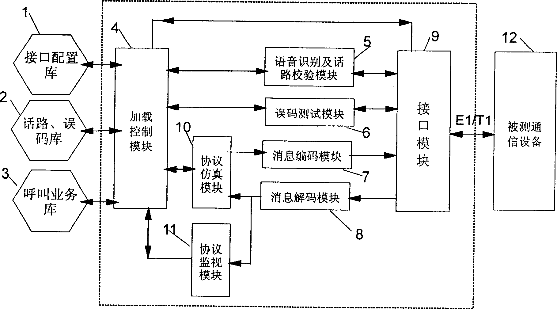
[0025] figure 1 It is a structural diagram of an embodiment of the device of the present invention. figure 1 Described is that communication equipment E1 / T1 interface service comprehensive test device comprises interface configuration database 1, speech path error code database 2, call service database 3, loading control module 4, protocol emulation module 10, protocol monitoring module 11, speech recognition and The voice path checking module 5 , the error code testing module 6 , the message coding module 7 , the message decoding module 8 , the interface module 9 , and the communication device 12 under test are also included. Among the above databases and modules,

[0026] The interface configuration database 1 is used to store the setting data of the interface module, such as the clock synchronization method of the physical layer, impedance matching, fram...


PUM


Abstract

The invention discloses a test device for integration testing service at E1, T1 interfaces. The device includes interface configuration database, error code database of telephone channel, calling service database, load control module, protocol emulation module, protocol monitoring module, speech recognition and telephone channel check module, error code testing module, message encoding module, message decoding module, and interface module. Through cooperation and interaction among above said modules realize following functions and parallel processing: unity of monitor and emulation, interface configuration, protocol stack, different kinds of types speech path test, signaling flow and calling service, DTMF dispatching number, identification of cue tone, and error code testing etc. The invention makes possible to enter performance testing, conformance testing and synthesis aptitude test from single functional test executed at currently.

Description

technical field [0001] The invention relates to the communication field, in particular to a test device for a communication system. Background technique [0002] With the continuous increase of the functions of the communication system, the number of electronic components and chips in the system is increasing, and the possibility of system failure is also increasing, so how to detect it in real time when the system is running normally and detect it in time Failure becomes very necessary. [0003] Among the many services that need to be tested, the E1 / T1 (E1: European standard PCM primary link, T1: North American standard PCM primary link, PCM: pulse code modulation) interface service is a more important one. In the prior art, monitoring and emulation are generally separated. Even if the data link layer adopts the same frame format, the emulation devices of the protocol stack are independent from each other and cannot share a hardware and or software platform. Such as NO7 s...

Claims


Application Information

Patent Timeline
IPC IPC(8): H04B17/336H04B17/391
Inventor 徐俊祥梅柳波杜文华陈略
Owner HUAWEI TECH CO LTD
Learn More