
Electronic accelerating pedal system with Legs strength regulating funtion

A technology of electronic acceleration and foot power, which is applied in the direction of control/regulation system, electric speed/acceleration control, power plant control mechanism layout, etc., and can solve the problem of deterioration of maneuverability

Inactive Publication Date: 2004-04-07
HYUNDAI MOTOR CO LTD
View PDF0 Cites 11 Cited by
  • Summary
  • Abstract
  • Description
  • Claims
  • Application Information

AI Technical Summary

Problems solved by technology

maneuverability

Method used


Image

  • Electronic accelerating pedal system with Legs strength regulating funtion
  • Electronic accelerating pedal system with Legs strength regulating funtion
  • Electronic accelerating pedal system with Legs strength regulating funtion

Examples


Embodiment Construction

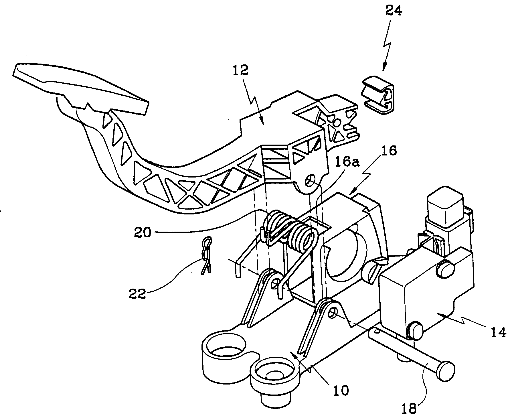
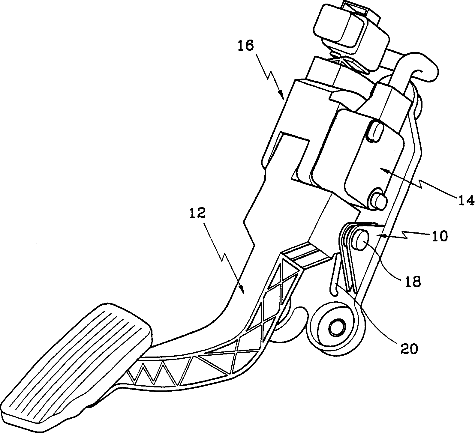
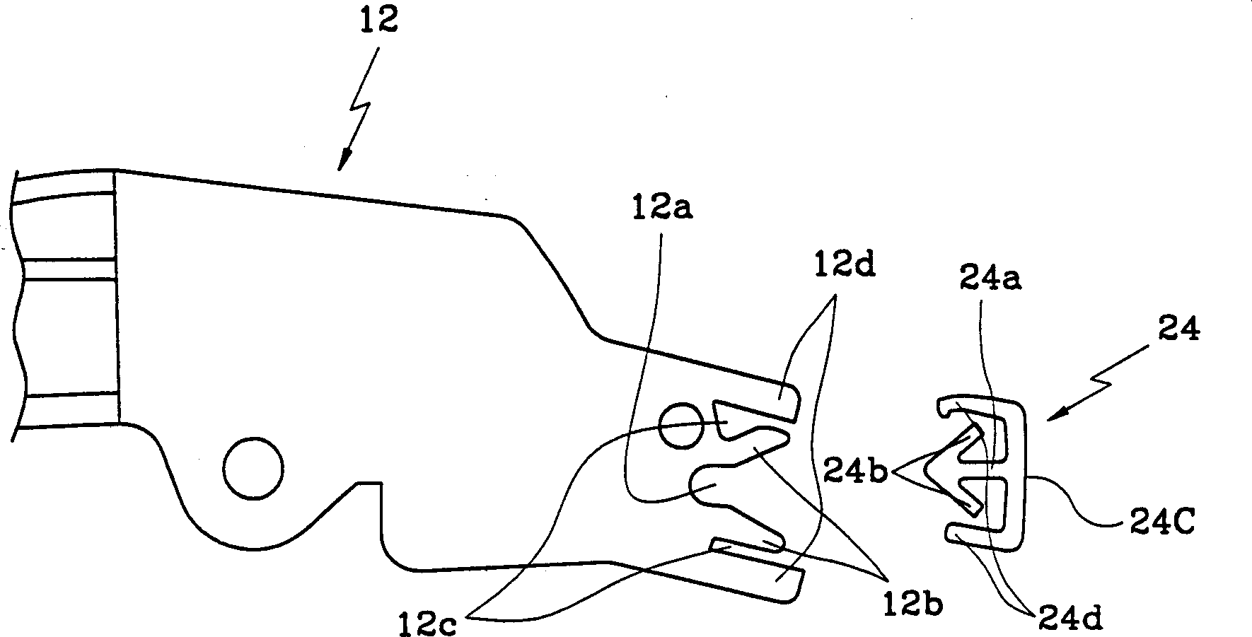
[0018] Such as figure 1 with 2 As shown, the electronic accelerator pedal system with foot power adjustment function of the present invention includes: a frame 10 fixed on the flower pan (flower panal) in the automobile interior; a pedal arm 12 pivotally mounted on the frame 10; The detection sensor 14 on one side of the support 10, such as a potentiometer, is used to electrically detect the angle of rotation of the pedal arm 12 during the rotation of the pedal arm 12; a foot force regulating device installed on the pedal arm 12 is used to generate a foot force that varies with the direction of rotation of the pedal arm 12; and a contact member 16 formed at the front end of the frame 10, which contacts the foot force adjusting device during the rotation of the pedal arm.

[0019] In addition, there is also a rotating (pivot) support fastening pin 18, which is installed on the base 10 and the pedal arm 12, so that the pedal arm 12 rotates between the base 10 and the pedal arm ...


PUM


Abstract

Provided is an electronic acceleration pedal arrangement having a treading force adjusting function of making treading force feeling of a driver different when the pedal is compressed or released to reduce fatigue feeling of driver by frequent acceleration operation to improve operability, in the electronic acceleration pedal arrangement for electrically detecting degree of turning by the treading force applied to the pedal and determining acceleration degree based on this. The electronic acceleration pedal arrangement comprises a pedal arm disposed turnably in the cabin, a detection sensor for detecting degree of turning at the turning time of the pedal arm, a treading force adjusting means disposed in the pedal arm and for changing the treading force depending on the turning direction of the pedal arm, and a contact member contacting with the treading force adjusting means at the turning time of the pedal arm.

Description

technical field [0001] The present invention relates to an electronic accelerator pedal system with foot force adjustment function, and more particularly to such an electronic accelerator pedal system in which the foot force is variable and adjustable relative to the stroke of the pedal arm during the process of depressing and releasing the accelerator pedal , thus improving the maneuverability of the accelerator. Background technique [0002] Accelerator control devices can generally be divided into mechanical and electronic types. The mechanical accelerator pedal system includes: an accelerator pedal pivotally installed in the car interior; a throttle mechanism installed in the engine air intake system; and a cable, used It is used to connect the accelerator pedal with the throttle valve mechanism to transmit the steering force. [0003] Meanwhile, the electronic accelerator pedal system includes: an accelerator pedal pivotally installed in the interior of the car, and a ...

Claims


Application Information

Patent Timeline
Patent Type & Authority Applications(China)
IPC IPC(8): B60K26/02F02D11/02G05G1/30G05G5/03
CPCG05G5/03G05G1/30Y10T74/20888Y10T74/20534B60K26/02
Inventor 金德基
Owner HYUNDAI MOTOR CO LTD
Learn More