


Quick Research
Generate reliable direction feasibility study reports for your R&D in just a few steps.

Technical Q&A
Discover and master advanced knowledge NOW. Basics, ideas, possibilities, all at once.

Find Solutions
As an expert in R&D theories, this can generate solutions to your technical problems instantly.

Evaluate Feasibility
Analyze your overall solution with one click, know your potential R&D risks in advance.

Monitor Landscape
Get weekly tech updates, stay abreast of the latest tech innovations and key insights.
Tank for draining a granular material/liquid mixture
A liquid mixture and granular material technology, applied to the feeding/discharging device of the settling tank, settling tank, container, etc., can solve the problems of uneven overflow and non-uniform surrounding of the drainage tank, etc.
- Summary
- Abstract
- Description
- Claims
- Application Information
AI Technical Summary
Problems solved by technology
Method used
Image

Examples
Embodiment Construction
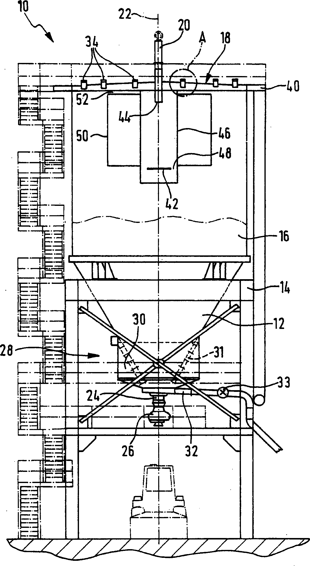
[0021] figure 1 A preferred embodiment of a drain tank 10 according to the invention is shown. The drain tank 10 comprises a conical lower part 12 supported in a frame structure 14 and a cylindrical upper part 16 mounted on the lower part 12 . The upper part 16 is provided with a cover 18 covering the top of the drain tank 10 . A filling tube 20 is provided through the cover 18 for filling the drain tank 10 with the particle / liquid mixture to be drained. The filling tube 20 passes through the cover 18 in such a way that it is coaxial with the vertical central axis 22 of the drain tank 10 . The lower part 12 terminates in an outlet section 24 provided with a shut-off member 26 . In the lower part 12 , upstream of the outlet portion 24 , there is means for separating liquid and particulate material, generally designated 28 . The separation device 28 comprises an annular collection chamber 30 for the drained liquid and a filter surface 31 (in figure 1 Shown in detail in dash...
PUM
 Abstract
Description
Claims
Application Information
 - R&D Engineer
- R&D Manager
- IP Professional
- Industry Leading Data Capabilities
- Powerful AI technology
- Patent DNA Extraction
Browse by: Latest US Patents, China's latest patents, Technical Efficacy Thesaurus, Application Domain, Technology Topic, Popular Technical Reports.
© 2024 PatSnap. All rights reserved.Legal|Privacy policy|Modern Slavery Act Transparency Statement|Sitemap|About US| Contact US: help@patsnap.com