
Sewing machine

A sewing machine and sewing technology, applied in the field of quilting machines, can solve problems such as wasting sewing products

Inactive Publication Date: 2004-03-31
HASHIMA
View PDF2 Cites 12 Cited by
  • Summary
  • Abstract
  • Description
  • Claims
  • Application Information

AI Technical Summary

Problems solved by technology

As a result, skipped stitches occur in the sewing pattern, thus wasting some seam work

Method used


Image

  • Sewing machine
  • Sewing machine
  • Sewing machine

Examples


Embodiment Construction

[0063] Refer below Figures 1 to 5 A plate for holding cloth in the quilting machine 10 of the first embodiment of the present invention will be described.

[0064] figure 1 It is a schematic diagram of the quilting machine according to the first embodiment of the present invention.

[0065] Such as figure 1 As shown, a roll of middle cloth 11 is disposed at one end of the quilting machine 10, and the middle cloth is a muslin cloth. The winding section 313 is provided at the other end of the quilting machine. The feed rollers 12 are disposed at the center of the quilting machine 10 at a predetermined pitch. The middle cloth sheet 11 is conveyed to a sewn product receiving section (not shown) adjacent to the winding section 313 through the plurality of rollers 12 and the winding section 313 . The lower cloth sheet 14 is sent below the middle cloth sheet 11 by the cloth feed roller 12 . The lower cloth panel 14 is conveyed to the sewn product receiving section through the ...


PUM


Abstract

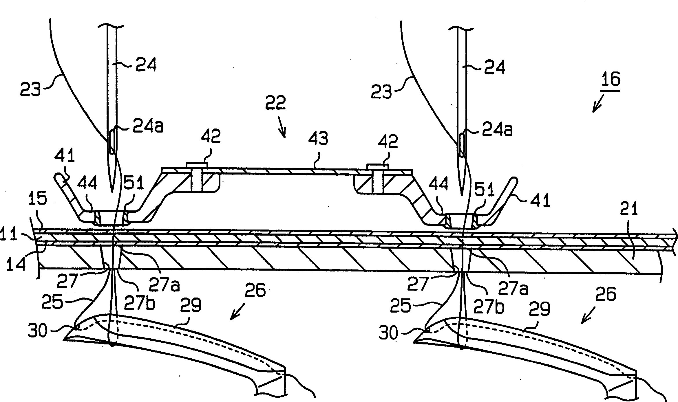
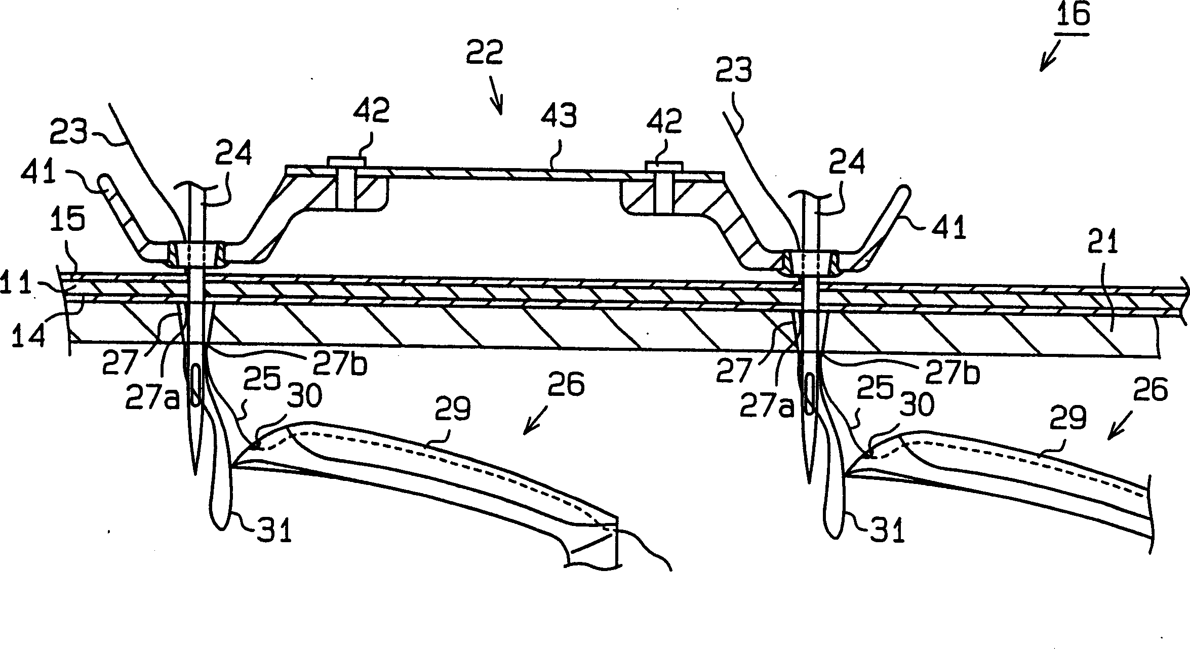
A sewing machine includes a supporting plate portion and a needle. The supporting plate portion contacts sewing fabric that is moved in a predetermined direction during a sewing operation. The needle is vertically moved between a top dead center above the supporting plate portion and a bottom dead center below the supporting plate portion. The supporting plate portion has a needle hole through which the needle passes. The lower end opening of the needle hole is larger than the upper end opening.

Description

technical field [0001] The present invention relates to a sewing machine, such as a quilting machine. Background technique [0002] In a standard sewing machine such as a quilting machine, a needle plate (a sewing cloth support plate) and a vertically movable clamping plate (a sewing cloth support plate) supported on the needle plate are included. Needle holes of the same diameter are formed in each of the needle plate and the clamp plate. The positions of the pinholes correspond to each other. When a piece of cloth clamped between the needle plate and the clamping plate is fed, the needle threaded with the upper thread reciprocates vertically between the upper dead center above the clamping plate and the lower dead center below the needle plate, simultaneously through the pinhole. Thus, a sewing pattern is formed on the cloth. [0003] In order to meet the requirements of shorter sewing times, the feeding speed of the cloth in the sewing zone has been significantly incr...

Claims


Application Information

Patent Timeline
IPC IPC(8): D05B11/00D05B29/00D05B33/00D05B55/06D05B55/10D05B55/14D05B57/02D05B61/00D05B63/00D05B65/00D05B69/32D05B69/36D05B73/12
CPCD05D2209/12D05B61/00D05B69/36D05B65/00D05B33/00D05B55/10D05B73/12D05B29/00D05B63/00D05B55/06D05B69/32D05B57/02D05B11/00D05B55/14
Inventor 加藤邦隆
Owner HASHIMA
Learn More