
Ultra-thin type centreless motor

An ultra-thin, wire-wound technology, applied in the direction of electrical components, electromechanical devices, electric components, etc., can solve the problems that the rotor cannot be thin and the starting voltage is large

Inactive Publication Date: 2004-03-17
TOKYO PARTS IND CO LTD
View PDF6 Cites 4 Cited by
  • Summary
  • Abstract
  • Description
  • Claims
  • Application Information

AI Technical Summary

Problems solved by technology

[0016] However, since the motor of Patent Document 3 is single-phase, the armature winding of the rotor needs to be positioned, so the rotor itself cannot be thin.
[0017] In addition, the structures of Patent Documents 5 and 6, which aim at thinness, are suitable for large radial dimensions. However, in the case of further miniaturization, since the structure of the hollow armature winding is 120 degrees, the arrangement of the 3 The phase gap of the wire-wound air-core armature winding is less than 2, especially in the radial press-in small motor, due to the torque fluctuation, that is, there is a position where the starting torque is small in the stop position of the rotor, so the starting voltage bigger
[0018] Furthermore, as in Patent Document 4, the casing part is crushed by pressing, and the motor that crushes and forms the concave part needs a considerable thickness of the casing. Therefore, in the prior art, the thickness is limited to 2.5 mm.

Method used


Image

  • Ultra-thin type centreless motor
  • Ultra-thin type centreless motor
  • Ultra-thin type centreless motor

Examples


Embodiment Construction

[0062] Specific implementation

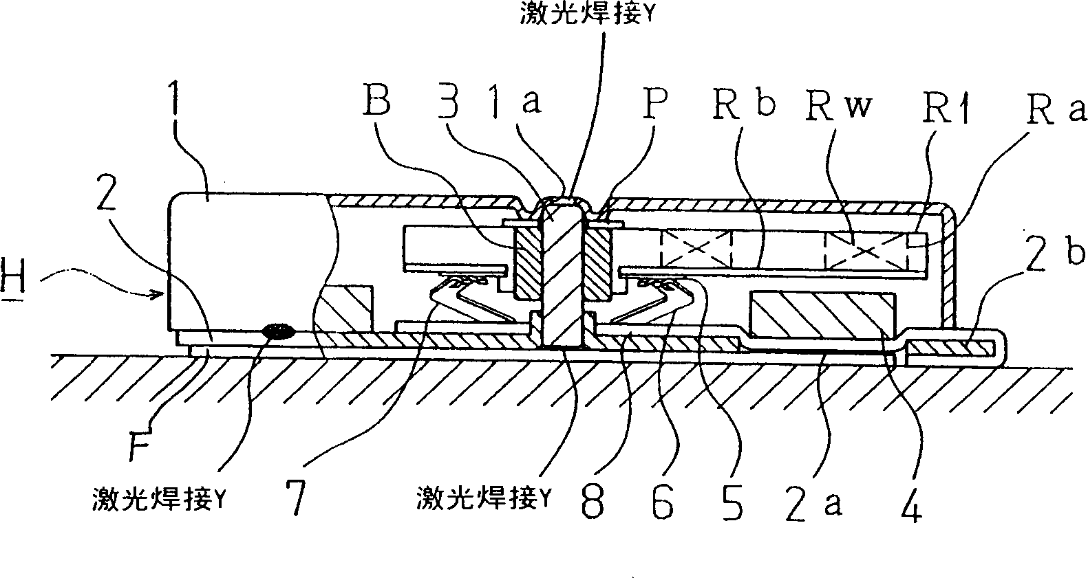
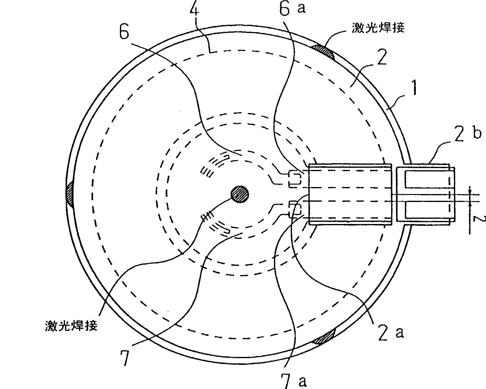
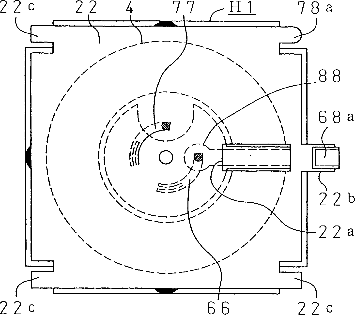
[0063] figure 1 It is a cross-sectional view of the ultra-thin coreless vibration motor as the first embodiment of the present invention. figure 2 To show figure 1 The bottom view of the characteristics of the power supply structure. image 3 for figure 1 Bottom view of a modification of the power supply structure. Figure 4 for figure 1 The top view of the eccentric rotor. Figure 5 It is a top view of a modified example of the same rotor. Figure 6 This is a cross-sectional view of an ultra-thin coreless vibration motor according to the second embodiment of the present invention. Figure 7 shows Figure 6 The bottom view of the characteristics of the power supply structure. Figure 8 for Figure 6 The top view of the eccentric rotor. Picture 9 for Figure 6 An explanatory diagram of the principle of rotation of the motor. Picture 10 It is a top view of another embodiment of an eccentric rotor. Picture 11 To be equipped with Picture 10 An...


PUM


Abstract

Motors are made thinner than conventional by adding a contrivance to a bracket. A housing composed of a case and a bracket is provided and an eccentric rotor and ring magnet are in the housing. A pair of brushes are provided with their base ends thereof anchored to a flexible base at the inside diameter of the magnet. The aforementioned flexible base leads to the outer periphery of the housing as a power-supply terminal, and an opening is provided in the part where the magnet is disposed in the housing. The flexible base leads to a side of the housing through the opening.

Description

Technical field [0001] The present invention relates to an improvement of a thin motor used in a silent calling device of mobile communication equipment, and more particularly to an improvement of an extremely thin coreless motor with a thickness of about 2 mm and an eccentric rotor mounted on the motor. Background technique [0002] With the demand for smaller and thinner mobile communication equipment, the parts mounted on the mobile communication equipment are also urgently required to be smaller and thinner. [0003] For example, recently, as extremely flat equipment, the size of the motor is also required to be 10 mm in diameter and 2 mm in thickness. [0004] In this case, the eccentric rotor also makes the last effort to the limit in thickness. [0005] As the advanced technology of a flat type vibration motor that only vibrates from the rotor, there are a motor in which three hollow armature windings are offset on one side (see Patent Document 1) and a hollow armature arr...

Claims


Application Information

Patent Timeline
Patent Type & Authority Applications(China)
IPC IPC(8): H02K7/075H02K1/00H02K5/00H02K7/065
CPCH02K5/145H02K5/225H02K7/063H02K2211/03
Inventor 山口忠男高城正弘下瀨川悟
Owner TOKYO PARTS IND CO LTD
Learn More