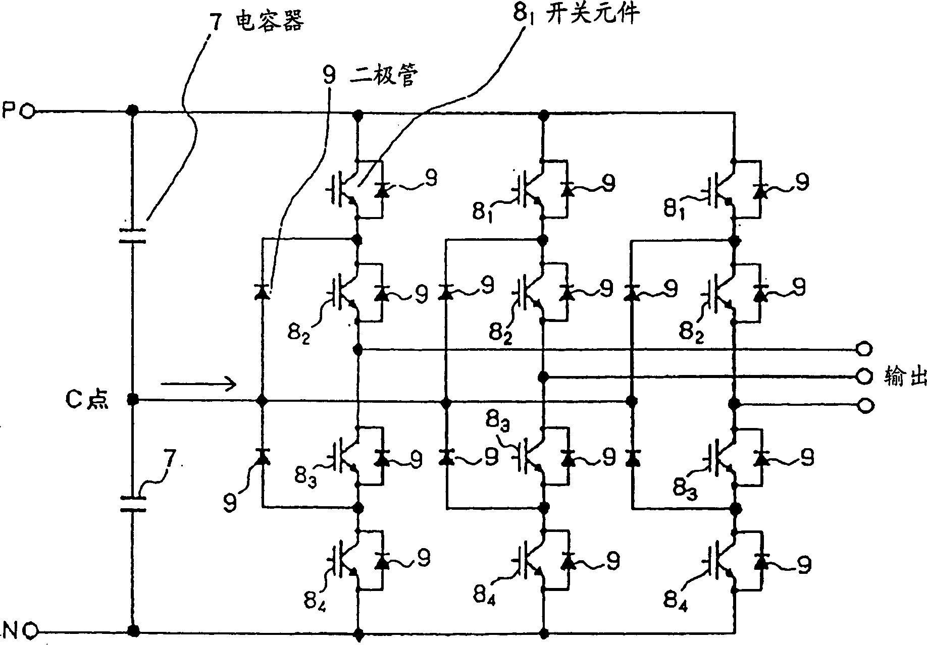
Three-level neutral point clamping PWM inverter and neutral point voltage controller
A neutral-point clamping and neutral-point voltage technology, which is used in output power conversion devices, irreversible DC power input to AC power output, electrical components, etc. Vulnerable to noise, etc.
- Summary
- Abstract
- Description
- Claims
- Application Information
AI Technical Summary
Problems solved by technology
Method used
Image
Examples
Embodiment 1
[0039] refer to Figure 7 A three-phase neutral point clamp type PWM inverter device according to Embodiment 1 of the present invention will be described. Figure 7 It is a block diagram showing the structure of a PWM pulse calculator applied to the three-phase neutral point clamp type PWM inverter device of this embodiment. Such as Figure 7 As shown, the three-phase neutral point clamped PWM inverter device of this embodiment includes a parameter calculator 101 for neutral point potential control, a vector time calculator 102 , a vector time register 103 and a PWM mode setter 104 .
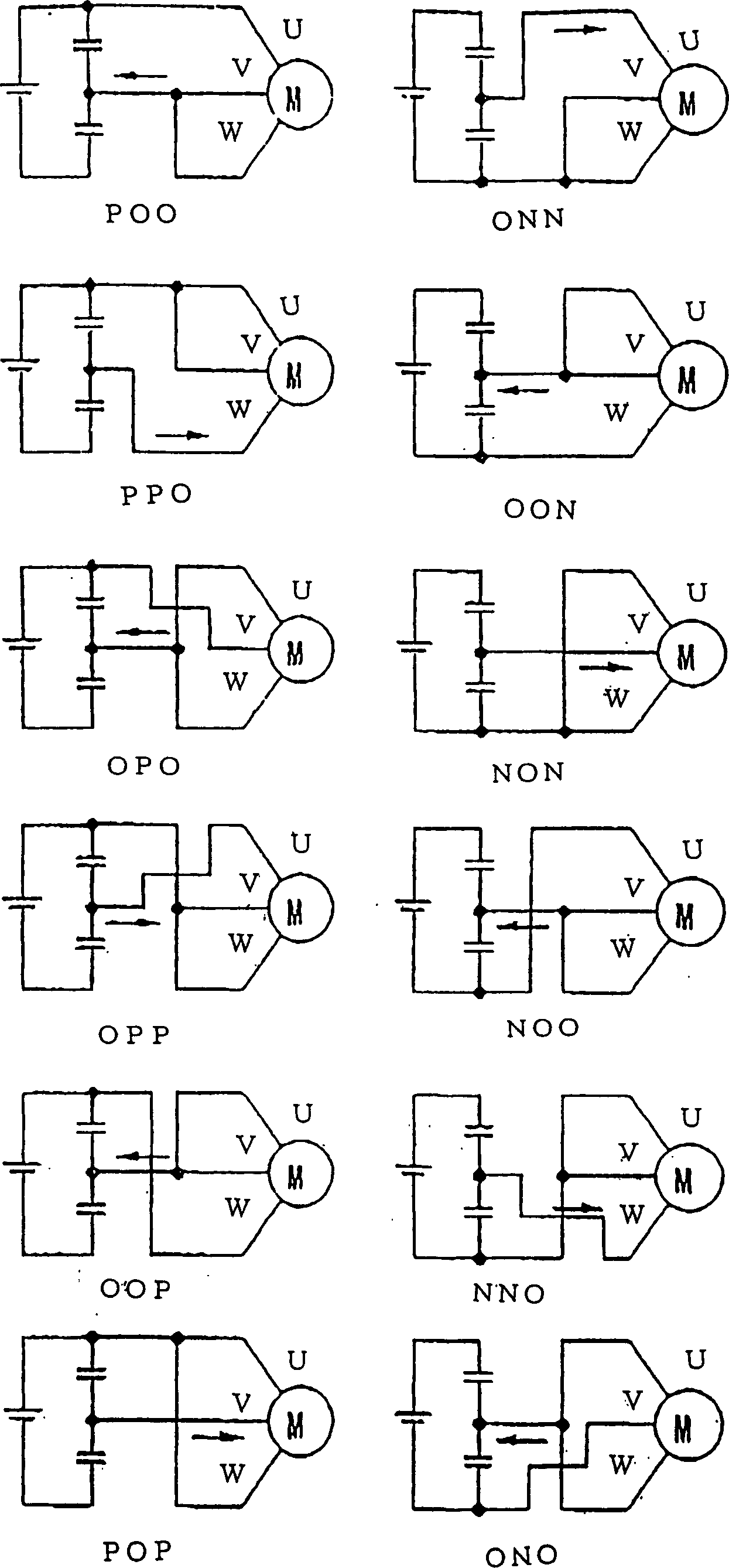
[0040] In the case of the three-phase neutral-point clamped PWM inverter device of this embodiment outputting the output voltage vector V, according to Figure 4 The shown vectors constitute the region (regions 1 to 6) in which the output voltage vector V exists, and output PWM pulses. Assume the classification of the vectors that make up the regions as Figure 4 As shown, the vector time ca...
Embodiment 2
[0109] The second neutral point voltage control device of the present invention will be described. Figure 8 is a block diagram showing the structure of the neutral point voltage control device of this embodiment. Such as Figure 8 As shown, the neutral point voltage control device of this embodiment is composed of a subtractor 1 , two comparators 2 , a calculation circuit 3 and an isolation circuit 10 .
[0110] Subtractor 1 output from the neutral point voltage V CN subtract the first reference voltage V ref1 value. The first reference voltage value V ref1 is a half voltage value (1 / 2·V PN ).
[0111] In addition to the first reference voltage value V ref1 In addition, a second reference voltage value V ref2 and the third reference voltage V ref3 . The second reference voltage value V ref2 and the third reference electric value V ref3 Such as Figure 9 Shown are negative and positive values, respectively.
[0112] A comparator 2 where the output value of the su...
Embodiment 3
[0119] Second, refer to Figure 10 A neutral point voltage control device according to Embodiment 3 of the present invention will be described. Figure 10 It is a block diagram showing the configuration of a neutral point voltage control device according to Embodiment 3 of the present invention. Such as Figure 10 As shown, the difference between the neutral-point voltage control device of this embodiment and the neutral-point voltage control device of the above-mentioned embodiments is that a comparator 4 is provided instead of two comparators 2, and a storage device 5 is provided instead of a calculation circuit 3 .
[0120] Comparator 4 input from the neutral point voltage V CN subtract the first reference voltage V ref1 value, the output value of the subtractor 1 is more than the second reference voltage value V ref2 Small case, in the second reference voltage value V ref2 Above the third reference voltage value V ref3 In the following cases, the ratio of the third ...
PUM
 Abstract
Description
Claims
Application Information
 - Generate Ideas
- Intellectual Property
- Life Sciences
- Materials
- Tech Scout
- Unparalleled Data Quality
- Higher Quality Content
- 60% Fewer Hallucinations
Browse by: Latest US Patents, China's latest patents, Technical Efficacy Thesaurus, Application Domain, Technology Topic, Popular Technical Reports.
© 2025 PatSnap. All rights reserved.Legal|Privacy policy|Modern Slavery Act Transparency Statement|Sitemap|About US| Contact US: help@patsnap.com


