
Thermal treatment system

A treatment system and heat treatment technology, applied in the field of heat treatment systems, can solve the problems of no patient procedures, long patient time, and a strong sense of oppression.

Inactive Publication Date: 2004-02-25
INSIGHTEC
View PDF2 Cites 20 Cited by
  • Summary
  • Abstract
  • Description
  • Claims
  • Application Information

AI Technical Summary

Problems solved by technology

If the procedure is MRI-guided, this means that the patient needs to remain still in the MRI machine for a longer period of time, which can be very stressful
At the same time, it is critical that all target diseased structures need to be resected (e.g. malignant cancerous tumors), in which case there are no shortcuts to the procedure in terms of patient comfort

Method used


Image

  • Thermal treatment system
  • Thermal treatment system
  • Thermal treatment system

Examples


Embodiment Construction

[0034] The invention will now be described in detail by way of example using an ultrasonic transducer as a means of delivering energy to a target lesion. However, it is apparent to those skilled in the art that other energy transfer devices may be used. For example, the invention is equally applicable to systems that generate heat using laser energy, radio frequency (RF), microwave energy, or electrical energy, as well as heating with ohmic coils or contact heating. The following preferred embodiments should therefore not be considered as limiting the invention to ultrasound systems.

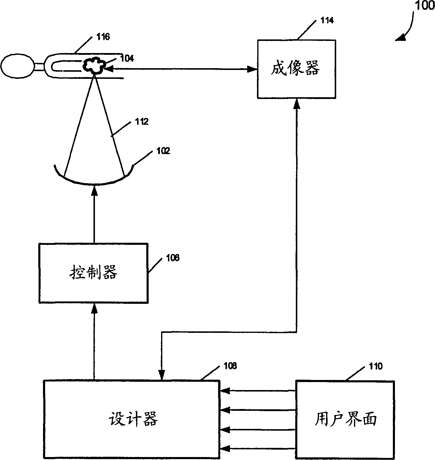
[0035] figure 2 A thermal therapy system 100 according to one embodiment of the invention is illustrated. The thermal treatment system 100 uses a heat applying element 102 to focus an energy beam 112 on a target mass 104 , which is typically a tumor in a patient 116 . In a preferred embodiment, the thermal therapy system 100 is a focused ultrasound system and the heat applying element 102 is ...


PUM


Abstract

A thermal treatment system including a heat applying element for generating thermal doses for ablating a target mass in a patient, a controller for controlling thermal dose properties of the heat applying element, an imager for providing preliminary images of the target mass and thermal images during the treatment, and a planner for automatically constructing a treatment plan, comprising a series of treatment sites that are each represented by a set of thermal dose properties. The planner automatically constructs the treatment plan based on input information including one or more of a volume of the target mass, a distance from a skin surface of the patient to the target mass, a set of default thermal dose prediction properties, a set of user specified thermal dose prediction properties, physical properties of the heat applying elements, and images provided by the imager. The default thermal dose prediction properties are preferably based on a type of clinical application and include at least one of thermal dose threshold, thermal dose prediction algorithm, maximum allowed energy for each thermal dose, thermal dose duration for each treatment site, cooling time between thermal doses, and electrical properties for the heat applying element. The user specified thermal dose prediction properties preferably include at least one or more of overrides for any default thermal dose prediction properties, treatment site grid density; and thermal dose prediction properties not specified as default thermal dose prediction properties from the group comprised of thermal dose threshold, thermal dose prediction algorithm, maximum allowed energy for each thermal dose, thermal dose duration for each treatment site cooling time between thermal doses, and electrical properties for the heat applying element.

Description

technical field [0001] The present invention mainly relates to a thermal treatment system, and in particular to a method and a device for controlling thermal dosage in the thermal treatment system. Background technique [0002] Thermal energy, such as that generated by high-intensity focused ultrasound (sound waves with a frequency above about 20 kilohertz), can be used to treat lesions in physiological tissue regions in a patient. For example, ultrasound can be used to remove tumors, thus avoiding surgery. For this purpose, it has been suggested that a piezoelectric transducer driven by an electrical signal to generate ultrasonic energy could be placed outside the patient's body as close as possible to the tissue to be resected. The transducer is geometrically shaped and positioned so that ultrasound energy is focused on a "focal zone" corresponding to a target tissue site within the patient, heating the target tissue site until it coagulates. The transducer can sequentia...

Claims


Application Information

Patent Timeline
Patent Type & Authority Applications(China)
IPC IPC(8): A61B18/20A61B17/00A61B18/00A61B18/04A61B18/18A61B19/00A61F7/00A61N5/02A61N5/06A61N7/02
CPCA61N7/02A61B2017/00084A61B19/50A61B2019/5236A61B34/10A61B2090/374
Inventor 大卫·弗罗因德利希雅各布·沃尔特曼罗尼·亚格利舒克·韦特克纳马·布伦纳
Owner INSIGHTEC
Learn More