Sound coder and sound decoder
A sound coding and coding technology, which is applied in speech analysis, code conversion, electrical components, etc., can solve the problem of losing the specialties of algebraic sound source, and achieve the effect of characteristic improvement
- Summary
- Abstract
- Description
- Claims
- Application Information
AI Technical Summary
Problems solved by technology
Method used
Image
Examples
Embodiment 1
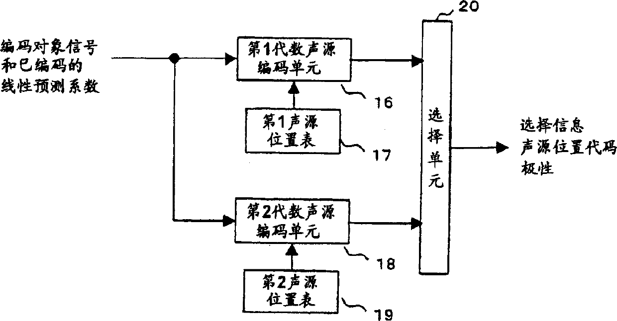
[0070] FIG. 1 shows the configuration of the driving sound source coding unit 5 of the speech coding apparatus of the present invention. The general structure of the audio coding device is the same as that in Fig.15. In the figure, 16 is a first algebraic sound source coding unit, 17 is a first sound source position table, 18 is a second algebraic sound source coding unit, 19 is a second sound source position table, and 20 is a selection unit.
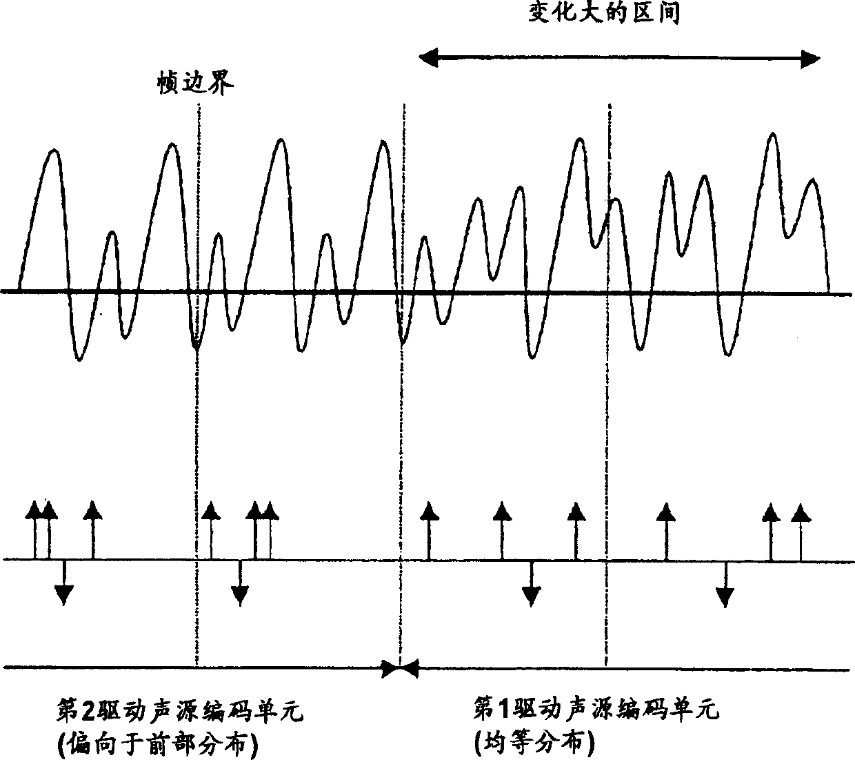
[0071] The first sound source position table 17 has a uniform position distribution in the frame, and the second sound source position table 19 has a position distribution in the first half of the frame.
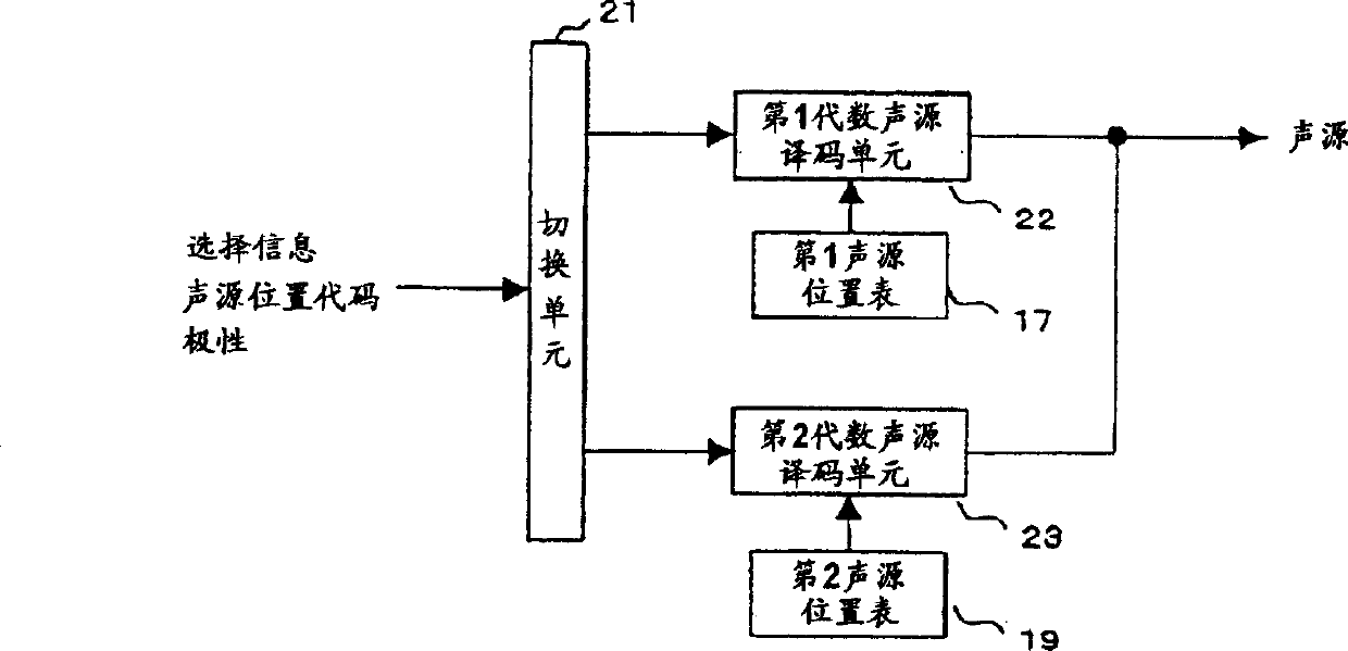
[0072] FIG. 2 shows the structure of the drive excitation decoding unit 12 of the audio decoding device of the present invention. The general structure of the audio decoding device is the same as that in Fig.16. In the figure, 21 is a switching unit, 22 is a first algebraic excitation decoding unit, and 23 is a second algebraic exc...
Embodiment 2
[0098] Fig. 5 is a diagram showing another example of the sound source position table used when the frame length of the sound source coding is 80 points.
[0099] FIG. 5( a ) is the first sound source position table 17 , and FIG. 5( b ) is the second sound source position table 19 . The first sound source position table 17 is the same as FIG. 3( a ), and is twice the sound source position in the sound source position table of Document 1 shown in FIG. 17 . That is, sound source position candidates are set every other sample. On the contrary, in the second sound source position table 19, 40 is added to each position value in the sound source position table of Document 1 shown in FIG. 17 . As a result, only the positions in the second half of the sound source frame are set as sound source position candidates. That is, no sound source position candidates are set for the first half of the sound source frame.
[0100] The configurations of driving excitation encoding section 5 an...
Embodiment 3
[0111] FIG. 7 shows the configuration of the driving sound source encoding unit 5 of the audio encoding device of the present invention. The general structure of the audio coding device is the same as that in Fig.15. In the figure, 16 is the first algebraic sound source coding unit, 17 is the first sound source position table, 18 is the second algebraic sound source coding unit, 19 is the second sound source position table, 24 is the judgment unit, and 25 is the selection unit .
[0112] FIG. 8 shows the structure of the drive excitation decoding unit 12 of the audio decoding device of the present invention. The overall structure of the audio decoding device is the same as that in FIG. 16 , the only difference is that the output of the linear prediction coefficient decoding unit 10 is supplied to the driving excitation decoding unit 5 and also to the driving excitation decoding unit 12 . In the figure, 26 is a switching unit, 22 is a second algebraic excitation decoding unit...
PUM
 Abstract
Description
Claims
Application Information
 - R&D Engineer
- R&D Manager
- IP Professional
- Industry Leading Data Capabilities
- Powerful AI technology
- Patent DNA Extraction
Browse by: Latest US Patents, China's latest patents, Technical Efficacy Thesaurus, Application Domain, Technology Topic, Popular Technical Reports.
© 2024 PatSnap. All rights reserved.Legal|Privacy policy|Modern Slavery Act Transparency Statement|Sitemap|About US| Contact US: help@patsnap.com


