Method of displaying tool track according to numerically controlled data and method for analyzing numerically controlled data
A tool path and display parameter technology, applied in the direction of digital control, program control, computer control, etc., can solve problems such as impossible, and achieve the effect of verifying accuracy
- Summary
- Abstract
- Description
- Claims
- Application Information
AI Technical Summary
Problems solved by technology
Method used
Image
Examples
Embodiment 1
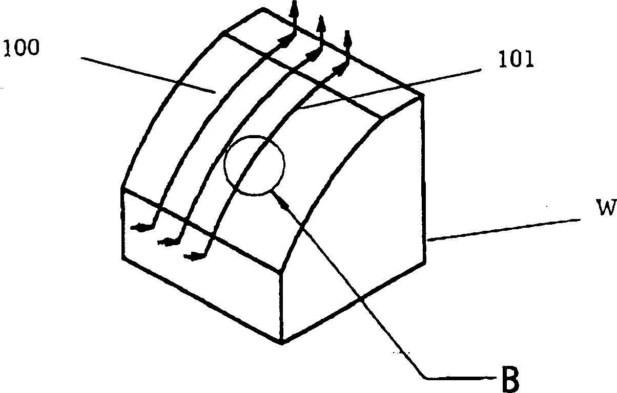
[0064] FIG. 5 is a block diagram showing a display device for implementing a display method according to a first embodiment of the present invention. XYZ axis data is input from an NC data input section 10 and sent to a trajectory data extraction section 11 . In the trajectory data extraction section 11, only tool trajectory data is extracted from the XYZ axis data, thereby eliminating other control data. The extracted tool trajectory data is supplied to a trajectory data analysis section 12, where desired display parameters are informed, which is a feature in this embodiment.
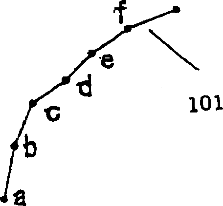
[0065] This embodiment is characterized in that the radius of curvature of the tool path is obtained with each of two or more NC data points extracted from a set of points collectively representing the tool path, and the numerical display parameter is assigned according to the obtained radius of curvature The point is assigned such that the point itself and its interrelationships around the point are ...
Embodiment 2
[0095] Figure 15 is a block diagram showing a display device for implementing a display method according to a second embodiment of the present invention. XYZ axis data are all input from an NC data input section 10 and sent to a trajectory data extraction section 11 . In the trajectory data extraction section 11, only tool trajectory data is extracted from the XYZ axis data, thereby eliminating other control data. The extracted tool trajectory data is supplied to a trajectory data analysis section 12, where desired display parameters are informed, which is a feature in this embodiment.
[0096] This embodiment is characterized in that the direction of movement of each detailed line segment relative to a specific axis, such as the Z axis selected from three axes, is evaluated to determine whether the movement points to a negative, positive or zero direction, and is different The display parameters are informed according to the determined direction. This variant allows the i...
Embodiment 3
[0130] Hereinafter, a third preferred embodiment will be described with reference to the drawings.
[0131] Figure 22 is a block diagram showing a display device for practicing the display method according to this third embodiment. XYZ axis data are all input from an NC data input section 10 and sent to a trajectory data extraction section 11 . In the trajectory data extraction section 11, only tool trajectory data is extracted from the XYZ axis data, thereby eliminating other control data. The extracted tool trajectory data is supplied to a trajectory data analysis section 12, where desired display parameters are informed, which is a feature in this embodiment.
[0132] This embodiment is characterized in that an area relative to a specific axis selected from three axes, i.e. the Z axis, is first divided into decomposed areas suitable for each predetermined width from the desired reference point, and The decomposition regions of each result are assigned different predeter...
PUM
 Abstract
Description
Claims
Application Information
 - R&D
- Intellectual Property
- Life Sciences
- Materials
- Tech Scout
- Unparalleled Data Quality
- Higher Quality Content
- 60% Fewer Hallucinations
Browse by: Latest US Patents, China's latest patents, Technical Efficacy Thesaurus, Application Domain, Technology Topic, Popular Technical Reports.
© 2025 PatSnap. All rights reserved.Legal|Privacy policy|Modern Slavery Act Transparency Statement|Sitemap|About US| Contact US: help@patsnap.com


