Micro-powder remover

A particle and vacuum container technology, applied in the direction of electrostatic cleaning, cleaning methods and appliances, ion implantation plating, etc., can solve the problems of reduced operating rate, huge, particle generation, etc., and achieve the effect of low installation cost

Inactive Publication Date: 2004-02-04
SHARP KK
View PDF0 Cites 1 Cited by
  • Summary
  • Abstract
  • Description
  • Claims
  • Application Information

AI Technical Summary

Problems solved by technology

Moreover, since the Totsukuda charging electrode is in contact with the particle collection plate for charging, the surface of the particle collection plate is damaged due to scratches, resulting in additional particle generation
[0007] Furthermore, since the mechanism for moving the charging rod is installed through the wall of the vacuum vessel, the device for charging the particle collection tray is complex and bulky and requires high assembly costs
Also, it is more expensive to operate due to the use of expensive gas used to aid combustion to dry clean
[0008] In addition, since the film preparation process must be stopped for a long time when the particle collection tray absorbs particles, the operating rate is reduced

Method used


Image

  • Micro-powder remover
  • Micro-powder remover
  • Micro-powder remover

Examples


Embodiment Construction

[0027] An apparatus for removing particles according to the present invention will be described in detail with reference to the accompanying drawings.

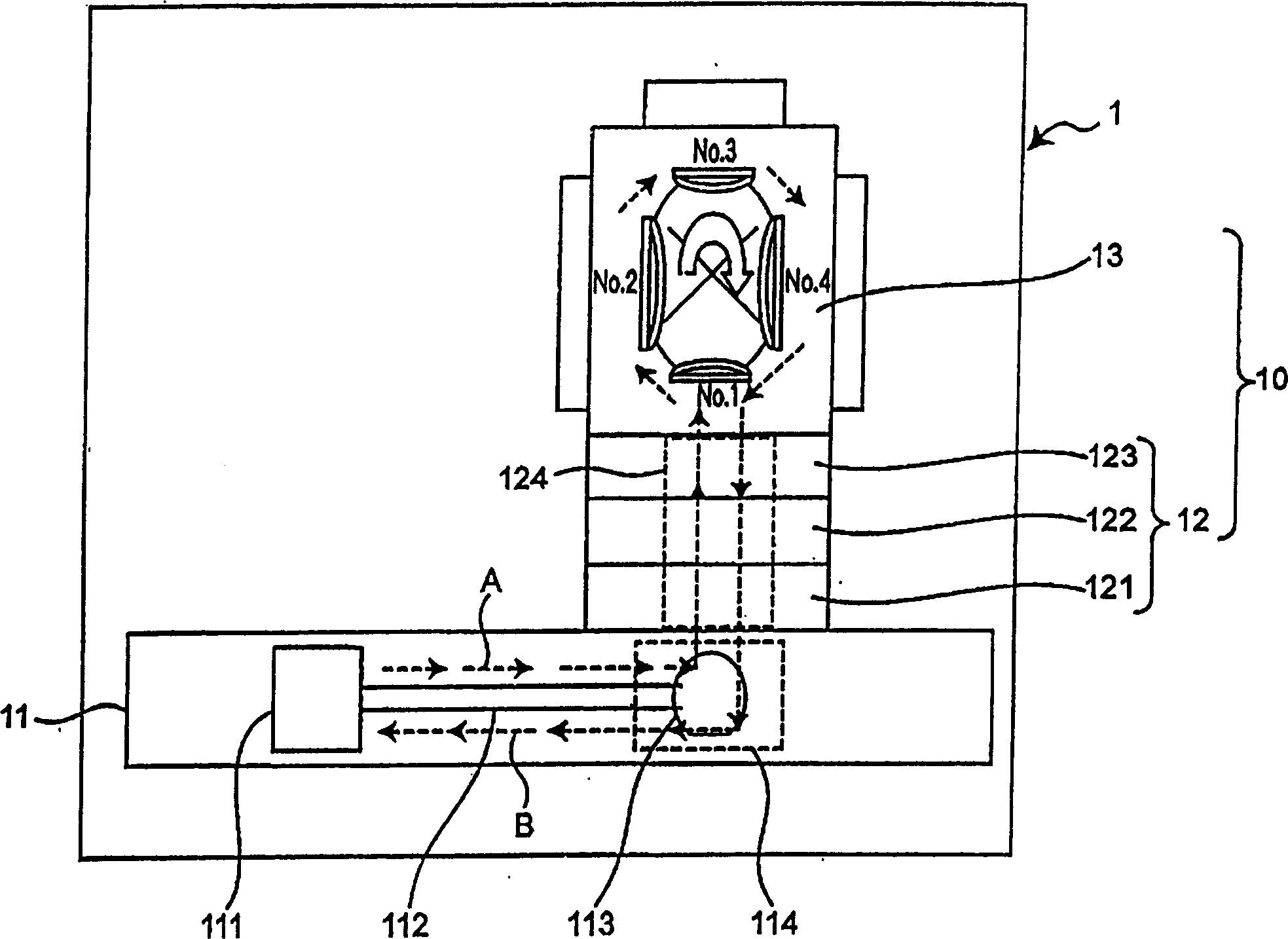
[0028] figure 1 is a plan view schematically illustrating the configuration of a sputtering apparatus including an apparatus for removing particles according to an embodiment of the present invention.

[0029] The sputtering apparatus 1 includes a transfer unit 11 for transferring a wafer; a pressure buffer unit 12 and a processing chamber 13 . The pressure buffer unit 12 and the processing chamber 13 constitute a vacuum container unit 10 . The sputtering apparatus 1 also includes a control unit, which controls the entire apparatus; a vacuum discharge system; a power supply unit and other components, although not shown in the figure, because they are not directly related to the present invention.

[0030] The transfer unit 11 transfers the wafer for thin film formation to the vacuum vessel unit 10 along an arrow A indicated...


PUM


Abstract

An object of the present invention is to provide an apparatus for removing particles which effectively eliminates particles in the vacuum container unit without degrading the rate of operation of the processing device, and is simple and inexpensive to embody. <??>The apparatus for removing particles in accordance with the present invention is for a processing device including a vacuum container unit having a plurality of chambers in which a predetermined process is performed on a wafer carried in by a conveyer unit in atmosphere. The apparatus comprises a charge neutralizing means for neutralizing charges generated on a surface of the wafer, the charge neutralizing means being mounted in a waiting-accommodation unit which constitutes a part of the conveyer unit, and a charging means for adsorbing particles in the vacuum container unit by electrostatic force, the charging means being mounted in the vacuum container unit.

Description

technical field [0001] The present invention relates generally to an apparatus for removing particles, and more particularly to an apparatus for removing particles for processing equipment including a vacuum container unit in which a wafer A predetermined process is carried out on the wafer, and the wafer is carried by the transfer unit. As a processing apparatus to which the present invention is applied, there is a sputtering apparatus used for manufacturing electronic devices such as semiconductor integrated circuits and liquid crystal panels. Background technique [0002] As electronic devices such as semiconductor integrated circuits and liquid crystal display panels become larger in size and their processing techniques become more microscopic, particles, such as dust in the air and fine grains in liquid chemicals during the manufacturing process, greatly significantly affect the characteristics or productivity of electronic devices. For this reason, the elimination of...

Claims


Application Information

Patent Timeline
Patent Type & Authority Applications(China)
IPC IPC(8): B08B6/00C23C14/56H01L21/00H01L21/02H01L21/304
CPCH01J2237/022H01L21/67028B08B6/00C23C14/564Y10S134/902H01L21/304
Inventor 佐佐木博司
Owner SHARP KK
Why Eureka
Try Eureka