
Vertical air conditioner

A vertical air conditioner and cavity technology, which is applied in air conditioning systems, heating methods, space heating and ventilation, etc., and can solve problems such as user troubles, excessive condensed water in shell parts, and different ambient temperatures of shell parts

Active Publication Date: 2015-11-25
GREE ELECTRIC APPLIANCES INC
View PDF8 Cites 12 Cited by
  • Summary
  • Abstract
  • Description
  • Claims
  • Application Information

AI Technical Summary

Problems solved by technology

There is a certain temperature difference between the air after heat exchange in the indoor heat exchanger and the ambient air outside the air conditioner, which will make the ambient temperature of the inner and outer surfaces of the shell parts different, and there is a certain temperature difference, especially in the air conditioner. When the device is in the cooling mode, a lot of condensed water will be formed on the shell parts, which will bring some troubles to the user.

Method used


Image

  • Vertical air conditioner
  • Vertical air conditioner
  • Vertical air conditioner

Examples


Embodiment Construction

[0032] Various embodiments of the invention will be described in more detail below with reference to the accompanying drawings. In the various drawings, the same elements are denoted by the same or similar reference numerals. For the sake of clarity, various parts in the drawings have not been drawn to scale.

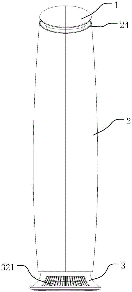
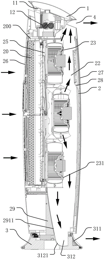
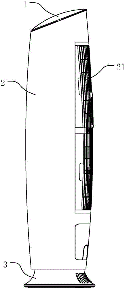
[0033] Note: In this application, the up-down direction is defined as: the direction extending from the bottom of the body 2 to the top cover assembly 1 is up, and the opposite direction is down; and, figure 1 The side where the air inlet 21 is located is defined as the rear side, and the side opposite to the air inlet 21 is defined as the front side.

[0034] Such as Figure 1-3 As shown, the vertical air conditioner in the present application includes a top cover assembly 1, a body 2 and a chassis 3, the top cover assembly 1 is arranged on the upper end of the body 2, and the chassis 3 is arranged on the lower end of the body 2, so The chassis 3 supports the whole ...


PUM


Abstract

The invention relates to a vertical air conditioner. The vertical air conditioner comprises an air supplying device, an installation plate, an air blocking plate and a front panel. The air blocking plate is arranged on the radial inner side of the front panel. The installation plate is arranged on the radial inner side of the air blocking plate. The installation plate and the air blocking plate are connected in a sealed manner. A body air way is formed between the installation plate and the air blocking plate. The air supplying device is installed on the installation plate. By means of the vertical air conditioner, the air blocking plate is arranged on the inner side of the front panel and can separate cold air in the air conditioner from the front panel, and therefore generation of condensate water on the outer side surface of the front panel can be reduced.

Description

technical field [0001] The invention relates to the technical field of vertical air conditioners, in particular to a vertical air conditioner. Background technique [0002] Existing vertical air conditioners generally include an indoor heat exchanger, a housing part and a fan. The housing part is provided with an air inlet and an air outlet. After the air enters the interior of the housing part through the air inlet, it enters the indoor heat exchanger. Perform heat exchange, and then blow out from the air outlet through the fan. There is a certain temperature difference between the air after heat exchange in the indoor heat exchanger and the ambient air outside the air conditioner, which will make the ambient temperature of the inner and outer surfaces of the shell parts different, and there is a certain temperature difference, especially in the air conditioner. When the device is in the cooling mode, a lot of condensed water will be formed on the shell parts, which will b...

Claims


Application Information

Patent Timeline
Patent Type & Authority Applications(China)
IPC IPC(8): F24F1/00F24F13/08F24F13/22
CPCF24F1/0003F24F13/084F24F13/22F24F2013/221
Inventor 潘龙腾王朝新吴舸姚俊华李德清金海元丘晓宏孟宪运张永成曾庆和温骊陈圣文杨杰臧允舒林裕亮
Owner GREE ELECTRIC APPLIANCES INC
Learn More