Air filter and manufacturing method thereof

An air filter, filter technology, used in chemical instruments and methods, filtration separation, separation methods, etc.

Inactive Publication Date: 2004-01-28
SHIKUFUSA
View PDF0 Cites 4 Cited by
  • Summary
  • Abstract
  • Description
  • Claims
  • Application Information

AI Technical Summary

Problems solved by technology

[0003] However, conventional air filters require more labor in manufacturing to form corrugations, cut to predetermined thicknesses and pleats

Method used


Image

  • Air filter and manufacturing method thereof
  • Air filter and manufacturing method thereof
  • Air filter and manufacturing method thereof

Examples


example

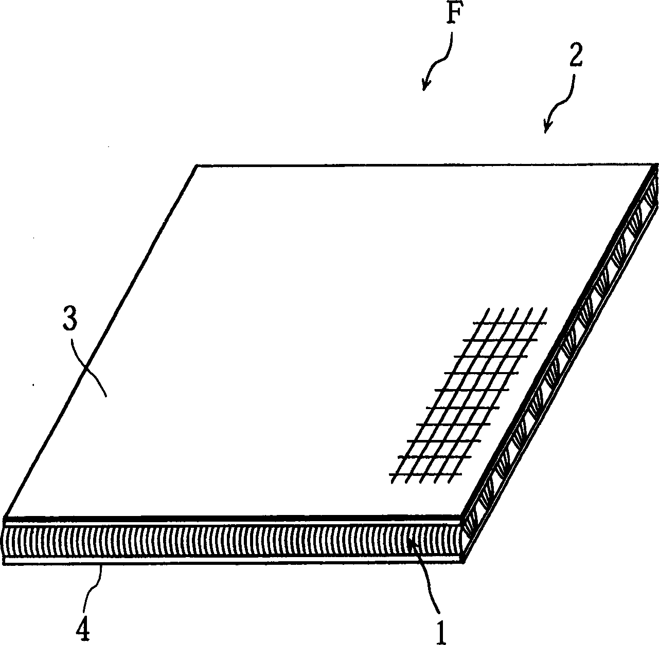
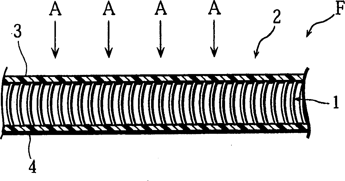
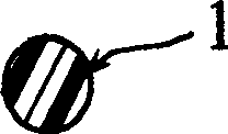
[0034] In the front view, two rectangular air filters (such as Figure 1 to 3 Said) as Example 1 and Example 2. Table 1 shows the dust collection efficiency of the air filter F. In Table 1, 0.3 μm, 0.5 μm, and 1.0 μm all indicate the size of dust (average diameter of particles).

[0035] Pressure loss Pa

Dust collection efficiency %

0.3μm

0.5μm

1.0μm

Example 1

3

12.25

19.80

32.81

Example 2

3

9.86

21.00

34.31

[0036] In addition, the two rectangular air filters with corrugated honeycomb structure of Comparative Example 1 and Comparative Example 2 have a front view size of 300mm×350mm, and the width between the two concave portions of the first member 26 of the circular waveform The size W is 3.6 mm, and the height H between two adjacent flat second parts 27 is 2 mm. Table 2 shows the dust collection efficiency of the air filter F. In Table 2, 0.3 μm, 0.5 μm, and 1.0 μm al...


PUM


Abstract

An air filter in which a thick sheet of textile of three-dimensionally knitted synthetic fiber thread is sliced at a middle position in a thickness direction and separated into a front face and a rear face. The front face or the rear face is one face side, and many short fibers are protruding from another face side. Further, the air filter is electrified as a whole.

Description

Technical field [0001] The present invention relates to an air filter and a manufacturing method thereof. The air filter is used to clean air for household or commercial electrical equipment that requires air circulation. Background technique [0002] As shown in FIG. 12, the conventional air filter has a corrugated honeycomb structure, in which a circular-wave first member 26 and a flat second member 27 are sequentially layered (stacked) to be received in a direction perpendicular to the surface of the filter The airflow, thereby collecting dust and deodorizing. And, as shown in FIG. 13, another conventional filter is composed of a pleated filter 28 and a plate-shaped filter 29. The pleated filter 28 is sequentially formed with a convex part and a concave part (cross section), The plate filter 29 is used to maintain the configuration of the filter 28 to receive the air flow in the direction of the arrow C. [0003] However, the conventional air filter requires more labor in manu...

Claims


Application Information

Patent Timeline
Patent Type & Authority Applications(China)
IPC IPC(8): B01D39/14B01D39/08B03C3/28D04B1/00D04B21/16
CPCY10S55/05Y10S264/48B03C3/28Y10S55/45Y10S55/43D04B21/04D10B2505/04B01D39/08
Inventor 小田岛贞雄
Owner SHIKUFUSA
Why Eureka
Try Eureka