
Light-emitting gun for handgun and rifle

A technology of light guns and rifles, applied in the field of light guns, can solve problems such as the inability of light bullets to shoot

Inactive Publication Date: 2004-01-14
NEC CORP
View PDF0 Cites 3 Cited by
  • Summary
  • Abstract
  • Description
  • Claims
  • Application Information

AI Technical Summary

Problems solved by technology

As a result, the light bullet cannot hit a target aimed with a gun sight

Method used


Image

  • Light-emitting gun for handgun and rifle
  • Light-emitting gun for handgun and rifle
  • Light-emitting gun for handgun and rifle

Examples


Embodiment Construction

[0048] Hereinafter, the trigger mechanism of the light gun of the present invention will be described with reference to the accompanying drawings.

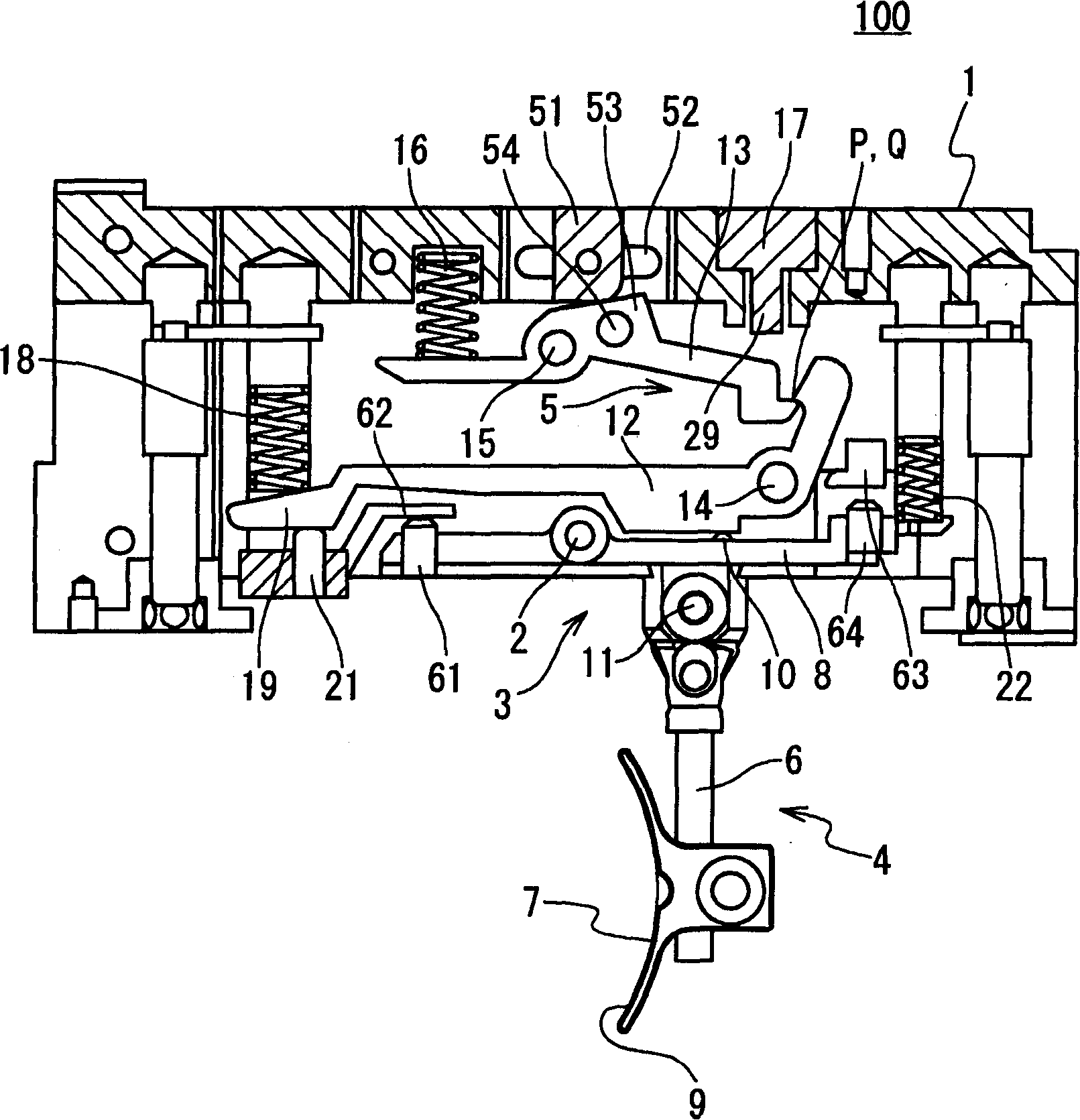
[0049] image 3 is a side sectional view of a trigger mechanism 100 of a light gun according to an embodiment of the present invention. The trigger device 100 includes a main body 1, a trigger operating system 3 and a firing pin operating system 5, wherein the trigger operating system 3 and the firing pin operating system 5 are arranged in the main body 1 of the trigger device of the light gun.

[0050] The trigger operating device 3 includes: a trigger lever portion 4 including a first lever portion 6 and a trigger blade 7 ; and a second lever portion 8 . Figure 4 and 5 is a view of the trigger lever part 4. The first rod part 6 includes a fixed rod part 6-1 and an adjustable rod part 6-2.

[0051] The main body 1 of the trigger device 100 is fixedly provided with a first rotating shaft 2 . The second lever portion 8 is rot...


PUM


Abstract

A light gun includes a trigger unit (100); a grip coupled to the trigger apparatus; and a barrel unit (31) coupled with the trigger apparatus. The trigger unit has a trigger and a hammer, and the barrel unit includes a light emitting unit (40) which emits a light bullet in response to generation of an impact by the hammer when a trigger operation is carried out by pulling the trigger.

Description

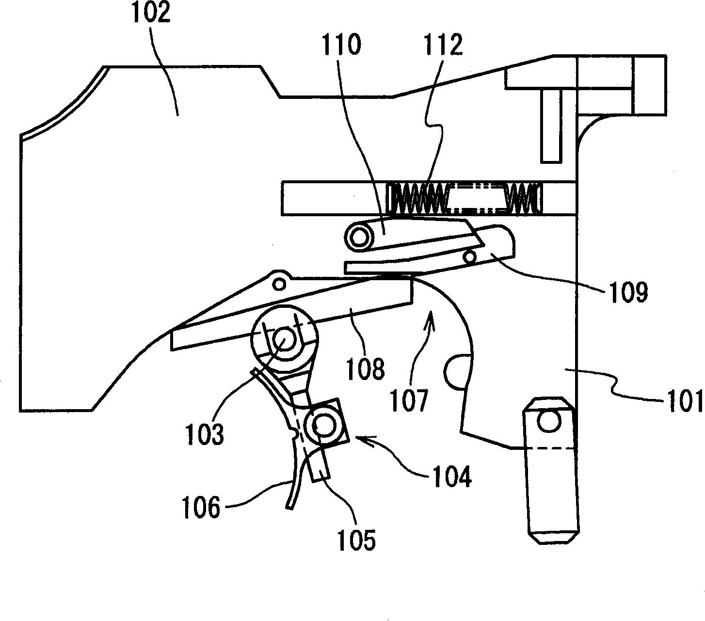
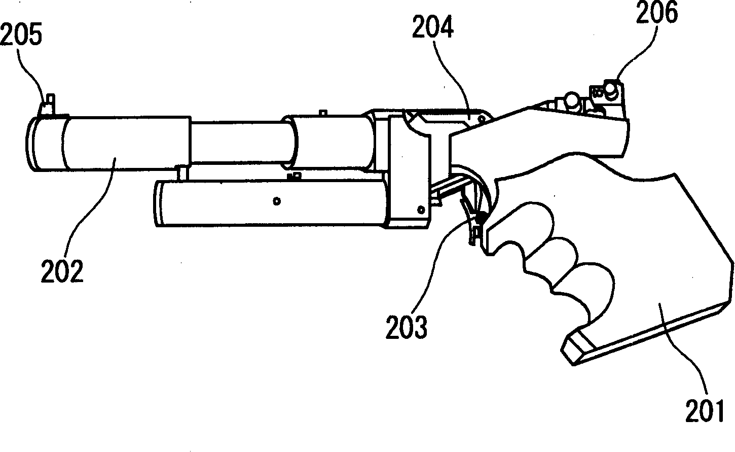
technical field [0001] The present invention relates to light guns for firing light projectiles. Background technique [0002] Shooting competition is a competition event in the Olympic Games. There are two types of shooting competitions: pistol competition and rifle competition. Pistol competitions are an extension of, and an effective facilitator of, police shooting training. Live ammunition is used in competitions and training. However, it is not desirable to use live ammunition from the standpoint of cost and safety, but to replace live ammunition with optical bombs such as short-wavelength laser bombs. When using smooth ammunition instead of live ammunition, it is necessary to change the trigger mechanism of the gun. [0003] figure 1 An example of a trigger mechanism for a conventional gun using live ammunition is shown. exist figure 1 , the barrel unit protrudes from the gun. The trigger device includes a handle portion 101 and a trigger system fixing portion 1...

Claims


Application Information

Patent Timeline
Patent Type & Authority Applications(China)
IPC IPC(8): F41A19/16F41A33/02F41G3/26
CPCF41A19/16F41A33/02Y10T436/106664F41A19/00
Inventor 乡古顺一
Owner NEC CORP
Learn More