
Low light loss matrix material for fibre-optical and its manufacturing method

A technology of base materials and manufacturing methods, applied in manufacturing tools, glass manufacturing equipment, optics, etc., can solve problems such as poor optical signal transmission quality

Inactive Publication Date: 2003-12-17
SHIN ETSU CHEM IND CO LTD
View PDF0 Cites 4 Cited by
  • Summary
  • Abstract
  • Description
  • Claims
  • Application Information

AI Technical Summary

Problems solved by technology

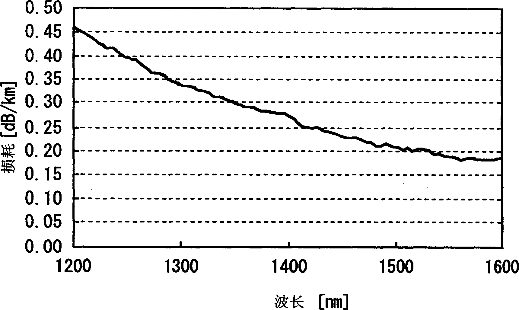
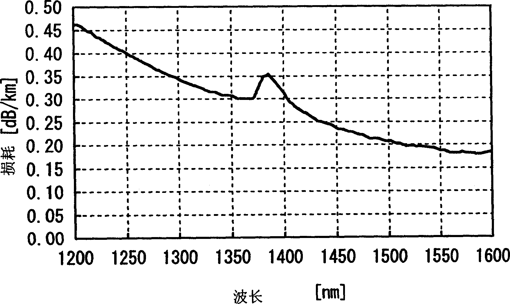
Therefore, the larger the absorption peak, the poorer the optical signal transmission quality

Method used


Image

  • Low light loss matrix material for fibre-optical and its manufacturing method
  • Low light loss matrix material for fibre-optical and its manufacturing method
  • Low light loss matrix material for fibre-optical and its manufacturing method

Examples


experiment example 1

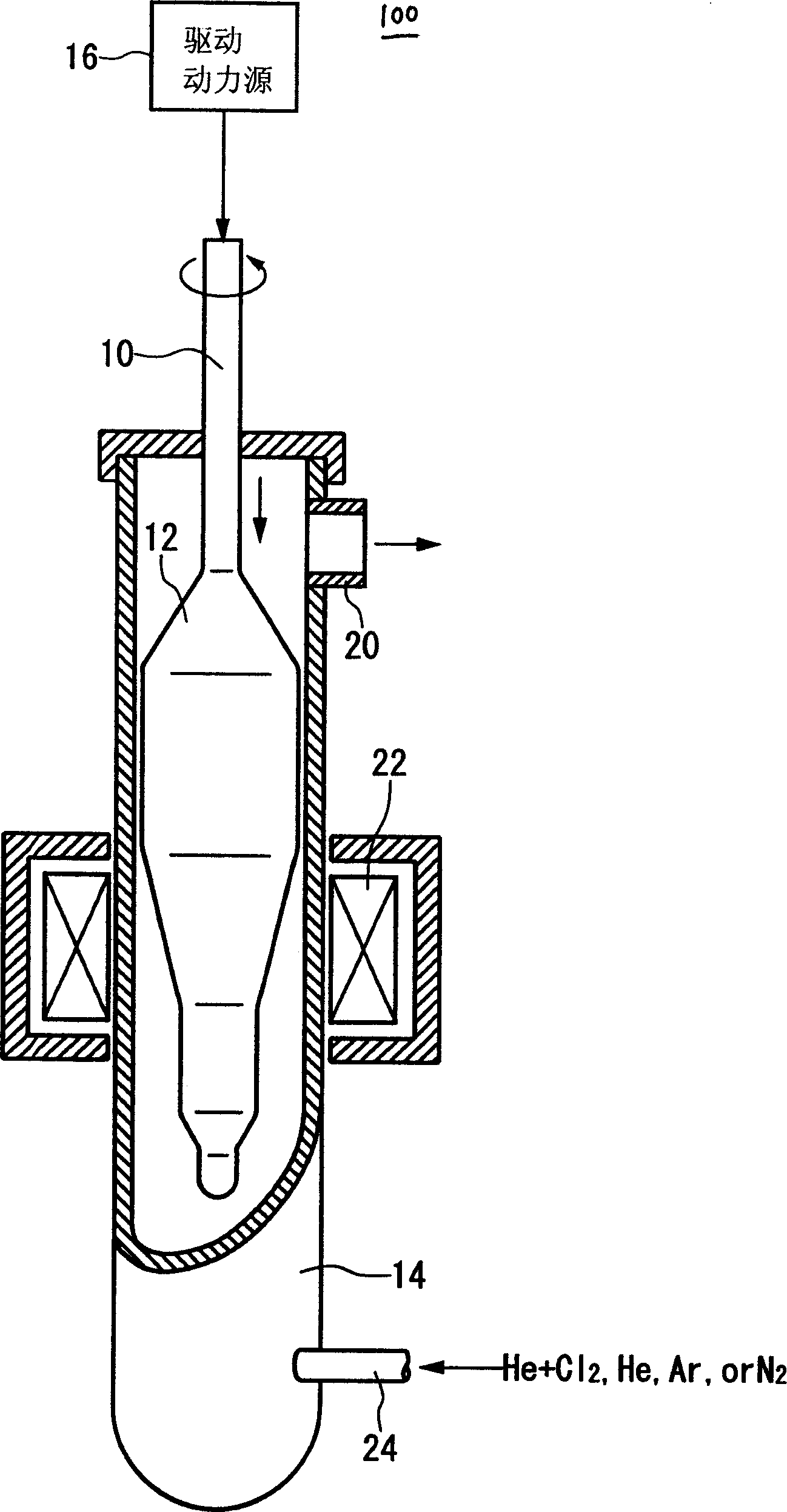
[0038] According to the vapor deposition (VAD) process, the porous matrix member can be formed by depositing glass particles. Then, the porous base member was hung vertically in the electric furnace. According to this configuration, in order to shape the optical fiber core member, the porous basic member is dehydrated at 1100°C in a chlorine and helium gas mixture atmosphere, purified at 1100°C in a 100% helium atmosphere, and then dehydrated in a 100% helium atmosphere Vitrification treatment at 1500°C.

[0039]The processing furnace used here includes a quartz tube. Porous or glass matrix material is placed in this quartz tube during operation, and the purpose is to ensure that the matrix material is sealed from the air when moving the matrix material up or down. A heater installed in the furnace heats a portion of the quartz tube. According to this configuration, the above-mentioned steps and processes are correspondingly completed when the base member passes through the...


PUM


Abstract

A method for manufacturing a base material of optical fibres having a desired ratio of core to clad, including forming a porous base material upon depositing glass particles, producing a core member upon dehydrating and vitrifying the porous base material, adding a clad member onto the core member, is characterized in that the method includes, a step of dehydrating the porous base material in an atmosphere of gas including helium and chlorine within an electric furnace; a step of vitrifying the porous base material in an atmosphere of inert gas including helium; and a step of providing a purging step of heating the porous base material in an atmosphere of inert gas mainly including helium between the dehydrating step and the vitrifying step.

Description

technical field [0001] The present invention relates to a method of manufacturing optical fiber matrix material by vapor axial deposition process (VAD). More precisely, it relates to a method for manufacturing a matrix material with a low light loss rate for an optical fiber. The optical absorption parameter caused by the moisture contained in the optical fiber matrix material manufactured by the present invention is much lower than that of the traditional matrix material. Background technique [0002] In general, the vapor deposition method is a well-known method for fabricating optical fiber substrate materials. According to this method, glass particles in the gas phase are deposited on the deposition side of the original member facing the gas source, while the original member is assembled on a shaft that can rotate and move upwards simultaneously, in order to manufacture an optical fiber consisting of a core and a cladding . [0003] The matrix material is a porous matr...

Claims


Application Information

Patent Timeline
Patent Type & Authority Applications(China)
IPC IPC(8): G02B6/00C03B37/012C03B37/014
CPCC03B37/01446C03B37/01466C03B37/018
Inventor 井上大小山田浩乙坂哲也平沢秀夫
Owner SHIN ETSU CHEM IND CO LTD
Learn More