


Quick Research
Generate reliable direction feasibility study reports for your R&D in just a few steps.

Technical Q&A
Discover and master advanced knowledge NOW. Basics, ideas, possibilities, all at once.

Find Solutions
As an expert in R&D theories, this can generate solutions to your technical problems instantly.

Evaluate Feasibility
Analyze your overall solution with one click, know your potential R&D risks in advance.

Monitor Landscape
Get weekly tech updates, stay abreast of the latest tech innovations and key insights.
Suction cleaner extension tube adjusting locking mechanism
A technology of locking mechanism and telescopic tube, applied in the direction of suction hose, etc., can solve problems such as unsafety and slipping, and achieve the effects of convenient operation, avoiding slipping, and safe and reliable use
- Summary
- Abstract
- Description
- Claims
- Application Information
AI Technical Summary
Problems solved by technology
Method used
Image


Examples
Embodiment 1
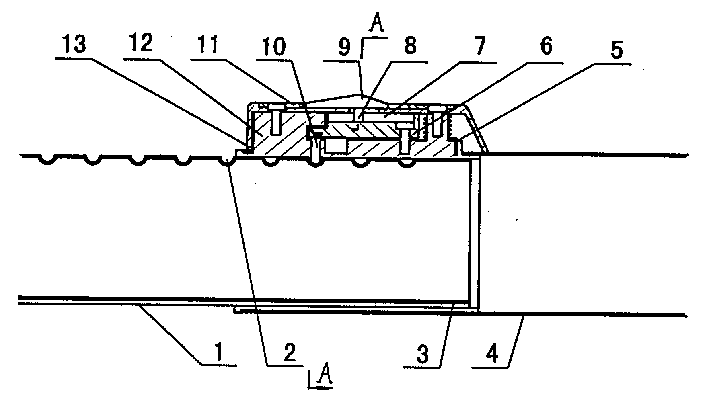
[0013] The telescoping tube of the vacuum cleaner of the present embodiment is as figure 1 and figure 2 As shown, one side of the inner tube 1 is formed with stepped tangential locking grooves 2, and the other side is formed with axial anti-rotation grooves 3. The outer tube 4 is sleeved outside the inner tube 1, and one end of the locking groove 2 on the inner tube 1 is grooved, and the locking seat 12 is fixed in the groove. The rear (right) end of this locking seat 12 is hinged fan-shaped pendulum block 6 by pins. The lower side of the pendulum block 6 is formed with a tangential slope, which abuts against the upper end of the locking post 10 inserted in the locking seat 12 .
[0014] In order to facilitate fitting with the inclined surface, the upper end of the locking post 10 is formed with chamfers consistent with the direction of the inclined surface. The lower end of the locking column 10 is made into a circular arc end, which can extend out of the locking seat 12 ...
Embodiment 2
[0021] The basic structure of this embodiment is the same as that of Embodiment 1, the difference is that an expansion plate is fixed on the push button 9, the periphery of this expansion plate falls in the shallow pool of the cover 13, and the upper surface is flush with the upper surface of the cover 13. In this way, the fixing screws on the cover plate 11 are hidden, and the appearance is more neat and beautiful.
PUM
 Abstract
Description
Claims
Application Information
 - R&D Engineer
- R&D Manager
- IP Professional
- Industry Leading Data Capabilities
- Powerful AI technology
- Patent DNA Extraction
Browse by: Latest US Patents, China's latest patents, Technical Efficacy Thesaurus, Application Domain, Technology Topic, Popular Technical Reports.
© 2024 PatSnap. All rights reserved.Legal|Privacy policy|Modern Slavery Act Transparency Statement|Sitemap|About US| Contact US: help@patsnap.com