Micrometer wave and milimeter wave guartic harmonic mixer

A fourth harmonic and millimeter wave technology, applied in the modulation transformation of electrical components, diodes, antennas, etc., can solve the problems of high manufacturing cost and use cost, and the mixer does not meet the needs of users to reduce costs, etc., to achieve cost reduction, The effect of performance improvement

Inactive Publication Date: 2003-09-24
CITY UNIVERSITY OF HONG KONG
View PDF0 Cites 15 Cited by
  • Summary
  • Abstract
  • Description
  • Claims
  • Application Information

AI Technical Summary

Problems solved by technology

[0004] Since both the fourth harmonic mixer and the fundamental wave mixer of the existing technology are used, the manufacturing cost and the use cost are very high, so under the situation

Method used


Image

  • Micrometer wave and milimeter wave guartic harmonic mixer
  • Micrometer wave and milimeter wave guartic harmonic mixer
  • Micrometer wave and milimeter wave guartic harmonic mixer

Examples


Embodiment Construction

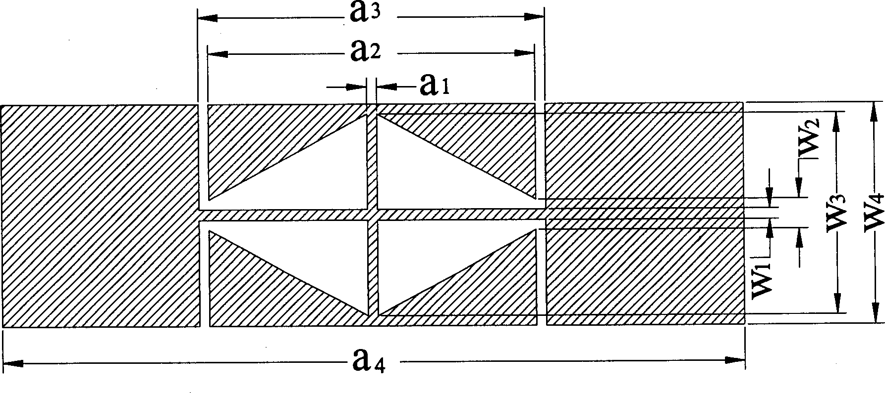
[0013] figure 1 It is a structural diagram of the compact microstrip resonant unit used in the fourth harmonic mixer of the present invention.

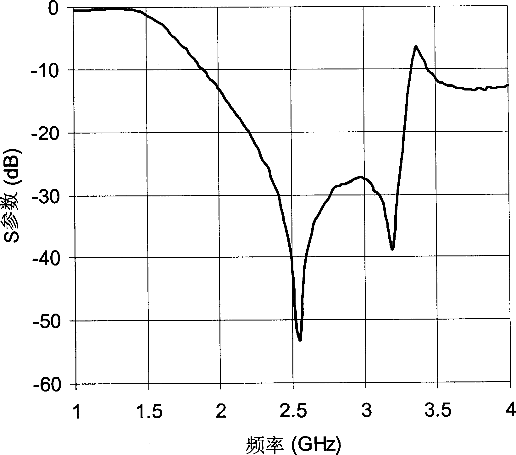
[0014] figure 2 is a typical transmission characteristic diagram of the compact microstrip resonant unit used in the fourth harmonic mixer of the present invention. It can be seen from the figure that compact microstrip resonant units with different frequencies have different characteristic curves. The present invention utilizes this feature and intentionally selects two compact microstrip resonant units with different characteristic curves to complete different tasks and realize the present invention.

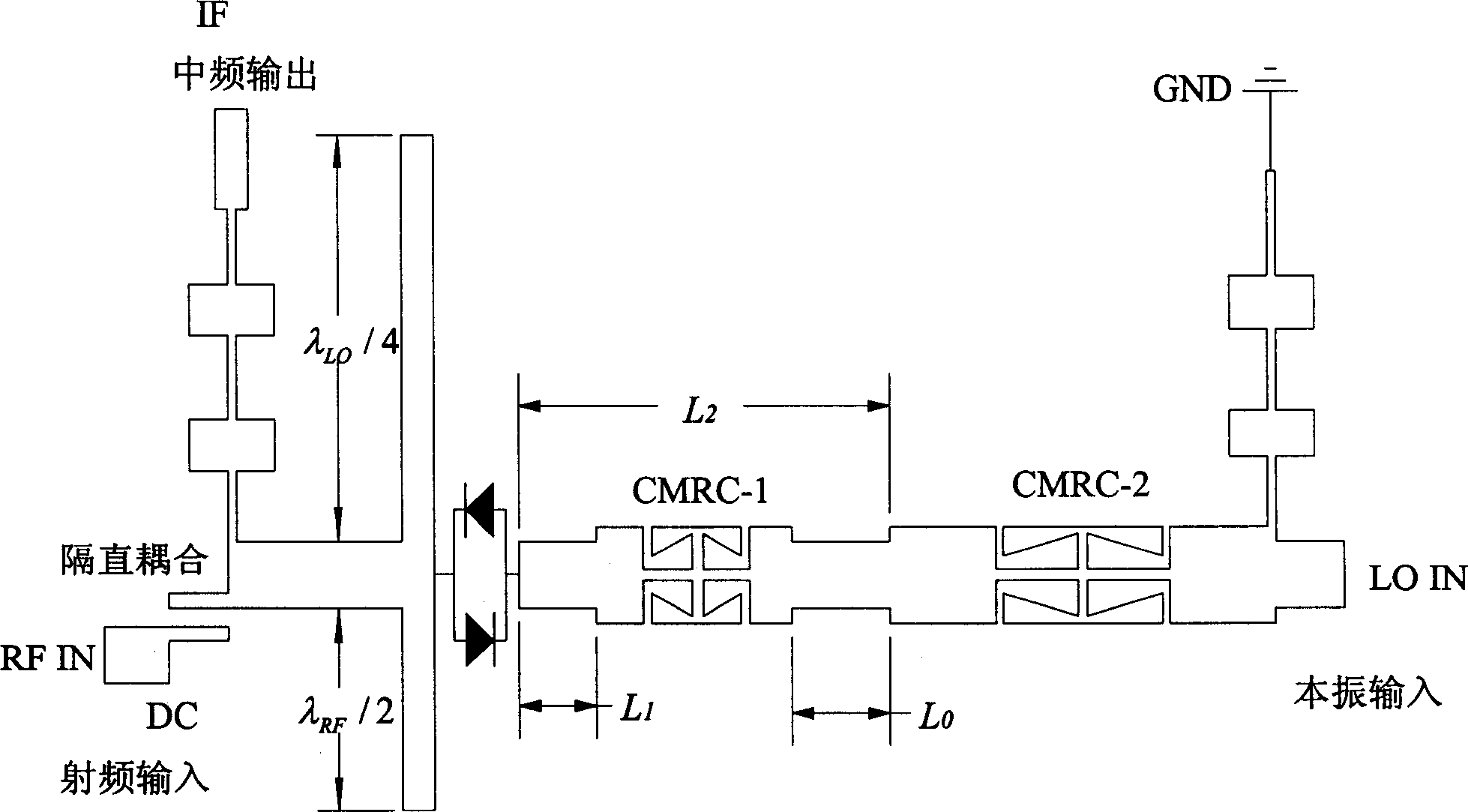
[0015] image 3 It is the structural diagram of the fourth harmonic mixer of the present invention. In this embodiment, the radio frequency signal (f RF ) is fed into the pair of Schottky reverse diodes from the RF input terminal at the left end through a DC blocking coupler. LO signal (f LO ) feeds this diode pair from the LO...


PUM


Abstract

A microwave and millimetric wave quartic frequency mixer is composed of a stopping direct coupler, two stage microstrip oper wires, a schottky reverse diode pair, two stage compact microphand resonance units, two microband high-low impedance line low pass filter. Since the used local frequency is 1/4 of the basic wave frequency mixer, its performance is increased greatly, and the compact microband resonance unit can either transfer the local signal and provide RF signal circuit or flexible adjust the idle terminal reactivity load, so as to suppress the idle frequency to reduce frequency conversion loss.

Description

technical field [0001] The invention relates to a mixer for microwaves and millimeter waves, in particular to a fourth harmonic mixer for microwaves and millimeter waves. Background technique [0002] Because the frequency conversion loss of the fourth harmonic mixer in the prior art is too high, most of the mixers in microwave and millimeter wave receiving and transmitting equipment still use fundamental wave mixers. A.Madjar in IEEE Trans.Microwave Theory Tech., vol.MTT-44, no.11, pp.1997-2000, Nov.1996. Titled "A novel general approach for the optimal design of microwave and millimeter wave subharmonicmixers" A theory of suppressing idler frequency to reduce conversion loss is proposed in the literature, and a second harmonic mixing result is given in a design example, but a method for obtaining a universal design in a simple way is not given. [0003] The inventors of the present invention are in IEEE Microwave and Guided Wave Letters, vol.10, no.10, pp.403-405, Oct.200...

Claims


Application Information

Patent Timeline
IPC IPC(8): H01Q13/00H01Q23/00H03D7/02
Inventor 薛泉岑鉴文陈志豪
Owner CITY UNIVERSITY OF HONG KONG
Why Eureka
Try Eureka