
Adjustable electronic thermostatic valve

An electronic constant temperature and adjustable technology, applied in the direction of control/regulation system, temperature control without auxiliary power supply, valve lift, etc., can solve problems such as damage, engine drop, and wire damage

Inactive Publication Date: 2003-08-20
HYUNDAI MOTOR CO LTD +1
View PDF0 Cites 10 Cited by
  • Summary
  • Abstract
  • Description
  • Claims
  • Application Information

AI Technical Summary

Problems solved by technology

[0007] However, the disadvantages of the electronic thermostatic valve described above are that the components of the valve are relatively easily damaged by the high temperature generated by the heating device, and its response time is relatively slow
Specific disadvantages of existing electronic thermostatic valves include, for example, heating defects in the wax or other components of the valve, and delays in operating the valve due to delays in heater heating and wax expansion in response to delays in providing electrical power to the heaters. Time
Also, during the process of sealing the thermostatic valve housing, the wires that power the heater may be damaged
Even if the entire sealing process does not cause any damage to the wires, the sealing material such as epoxy resin will fall or break due to the vibration of the engine
[0008] In case the thermostatic valve works in safe mode due to the damage of electronic components, the continuous high temperature of the engine is likely to cause fatal damage to the engine

Method used


Image

  • Adjustable electronic thermostatic valve
  • Adjustable electronic thermostatic valve
  • Adjustable electronic thermostatic valve

Examples


Embodiment Construction

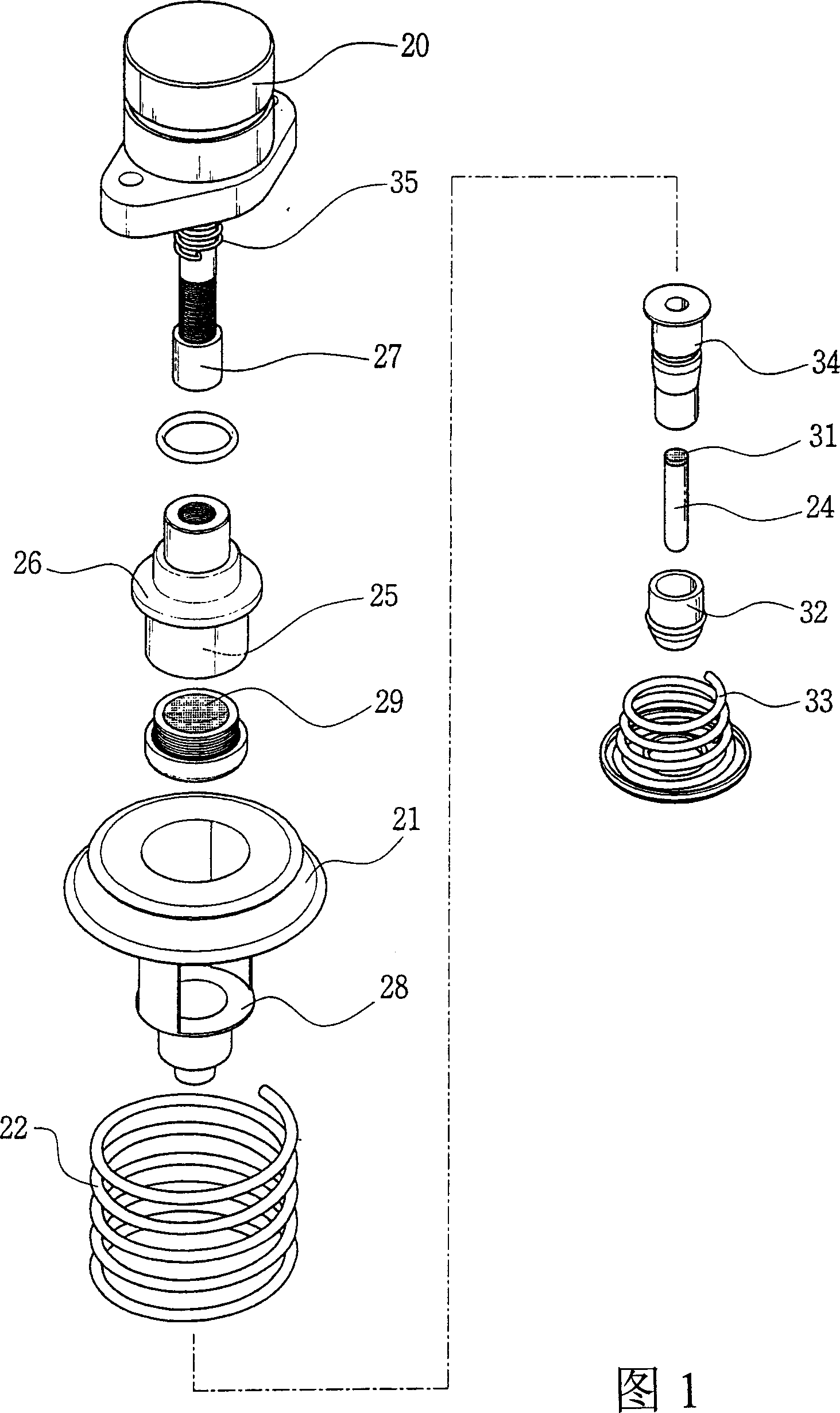
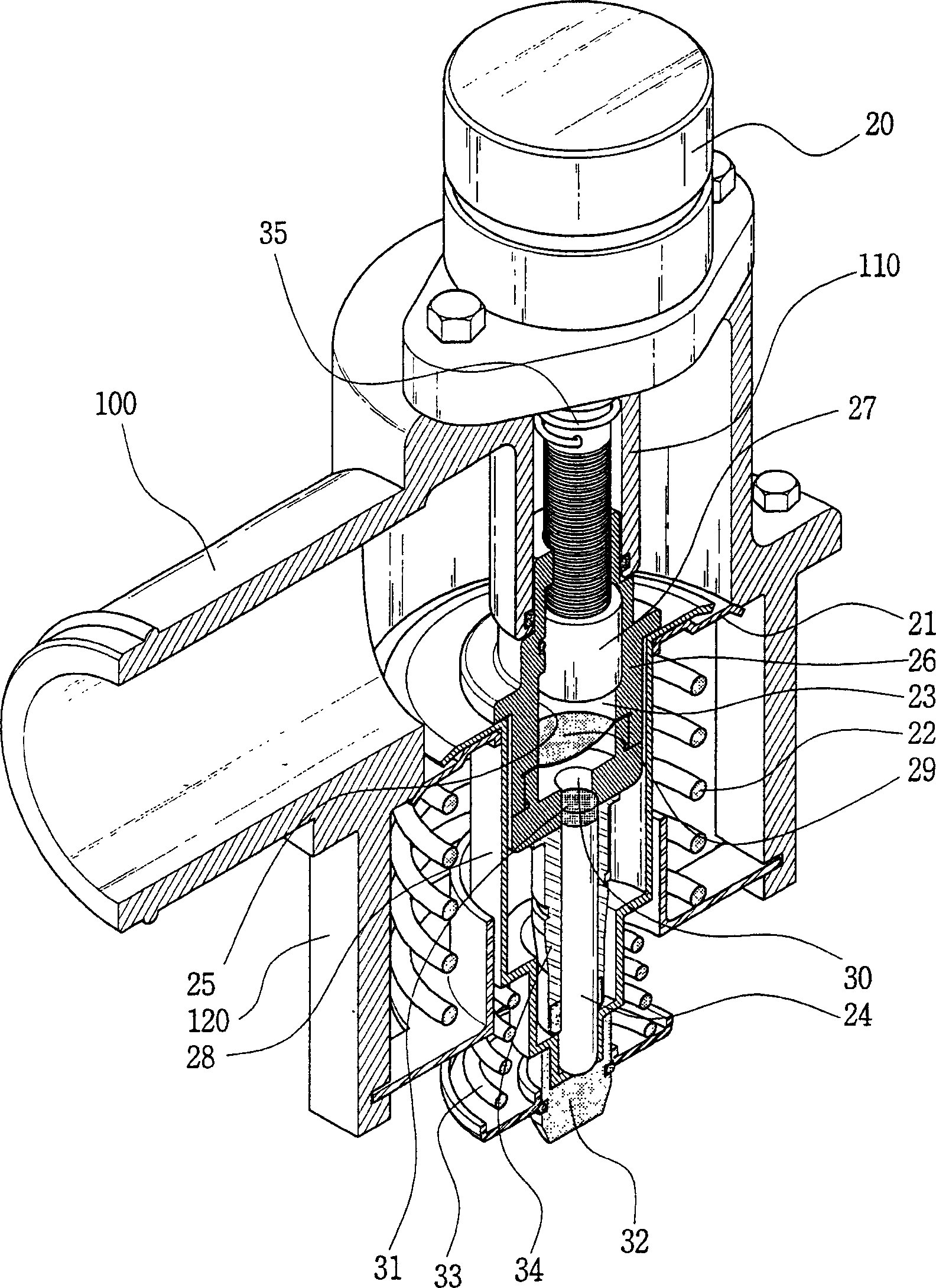
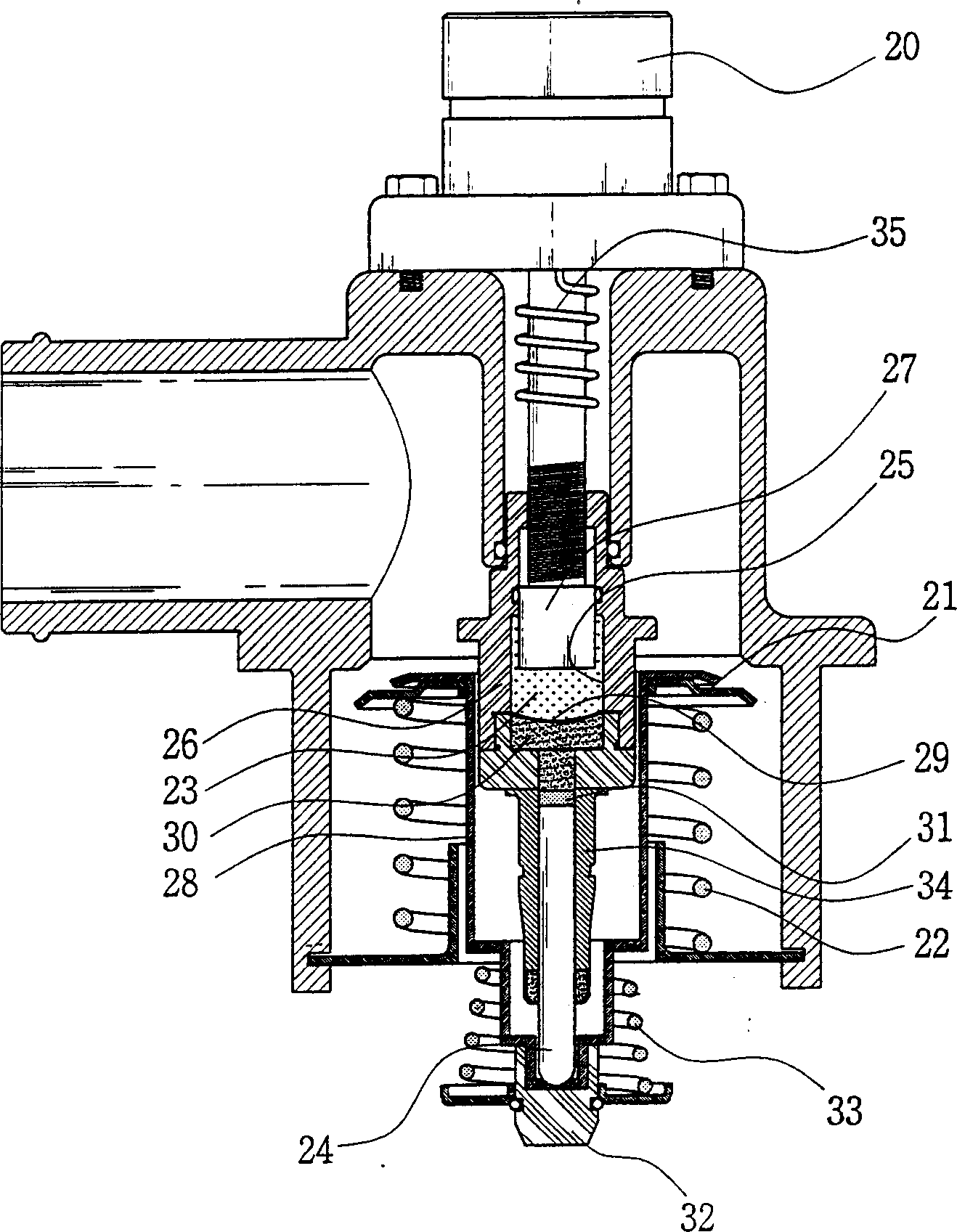
[0021] Next, a preferred embodiment of the present invention will be described in detail with reference to the accompanying drawings. Figure 1 and figure 2 As shown, the adjustable electronic thermostatic valve according to an embodiment of the present invention has a driving device 20 controlled by an electronic control unit (ECU) (not shown) on the vehicle and a container 26 with a chamber 25 for containing Chamber 25 is used to accommodate expandable thermal element 23 . The rod 27 of the drive means 20 is partially inserted into the chamber 25 and engages with the upper part of the container 26 by threads. Thus, the rotational movement generated by the drive device 20 is converted into a linear movement of the rod 27 via the thread on the rod 27 and the container 26 . The drive means used to generate motion in response to an input of electrical energy can be selected by one skilled in the art. Suitable devices include, for example, linear stepper motors, DC motors or li...


PUM


Abstract

The present invention relates to an adjustable electronic thermostat valve comprising an actuating means (20) provided with a rod (27) for stroking a chamber of an expendable thermal element, so that temperature at which the thermostat valve opens can be easily adjustable based on driving condition of an automobile by changing the volume of the chamber of the expendable thermal element, whereby a cooling efficiency of the engine is maintained in optimized range. As a result, emission of exhaust gas and consumption of fuel is significantly reduced.

Description

technical field [0001] The present invention relates to a thermostatic valve used in an automobile cooling system, and more particularly to an adjustable electronic thermostatic valve. Background technique [0002] Under normal circumstances, a thermostatic valve is installed between the car engine and the radiator. Its function is to keep the temperature of the coolant in an optimal range by controlling the flow of coolant flowing to the engine according to the change of the coolant temperature. Inside. The thermostatic valve ultimately controls the temperature of the engine by controlling the flow of coolant. [0003] The traditional thermostatic valve widely used at present is mechanical, which opens and closes the valve according to the up and down movement of the piston, and the expansion and contraction of the thermal expansion element are transmitted through the movement of the piston. For example, a mechanical thermostatic valve might include a paraffin actuator. ...

Claims


Application Information

Patent Timeline
IPC IPC(8): F01P7/16G05D23/13
CPCF01P2031/32F01P7/167G05D23/1921F01P7/16
Inventor P·W·刘
Owner HYUNDAI MOTOR CO LTD
Learn More