
Cervical spine traction device, equipment and method

a cervical spine and traction device technology, applied in the field of cervical spine traction device, equipment and method, can solve the problems of neck muscles in a non-coordinated stress state, degenerative or damaged muscles and ligaments, tedious and time-consuming,

Pending Publication Date: 2021-06-24
NAT TAIPEI UNIV OF TECH
View PDF7 Cites 1 Cited by
  • Summary
  • Abstract
  • Description
  • Claims
  • Application Information

AI Technical Summary

Benefits of technology

The present invention provides a cervical spine traction device, equipment and method with a main controller that has a program code to determine the optimal traction data based on the user's weight and height. The device can sense the user's temperature and massage the neck to relax the tension force of the neck muscle and correct the cervical spine. The and massage the neck to relax the tension force of the neck muscle and correct the cervical spine. The technical effects of the invention are improved traction efficiency, comfort, and improved user experience.

Problems solved by technology

The patients having degenerative diseases or injuries in cervical spines usually work the desk for a long time, and their cervical spines maintains a in a specific state for a long time, which causes the neck muscles to be in a non-coordinated stress state for a long time, such that the muscles and ligaments in the back of the neck may be damaged or degenerative.
However, traditional traction devices use multiple steps to measure and calculate corrected stretching forces, and it is not only tedious and time-consuming, but also not economical.
Therefore, to achieve objectives of fast operation and high precision, how to use an innovative hardware design to effectively achieve the measurement through a one-time device and to provide the required corrected stretching force and time is still an important issue which the relevant industry developers and rehabilitation researchers work hard to overcome.

Method used


Image

  • Cervical spine traction device, equipment and method
  • Cervical spine traction device, equipment and method
  • Cervical spine traction device, equipment and method

Examples


Embodiment Construction

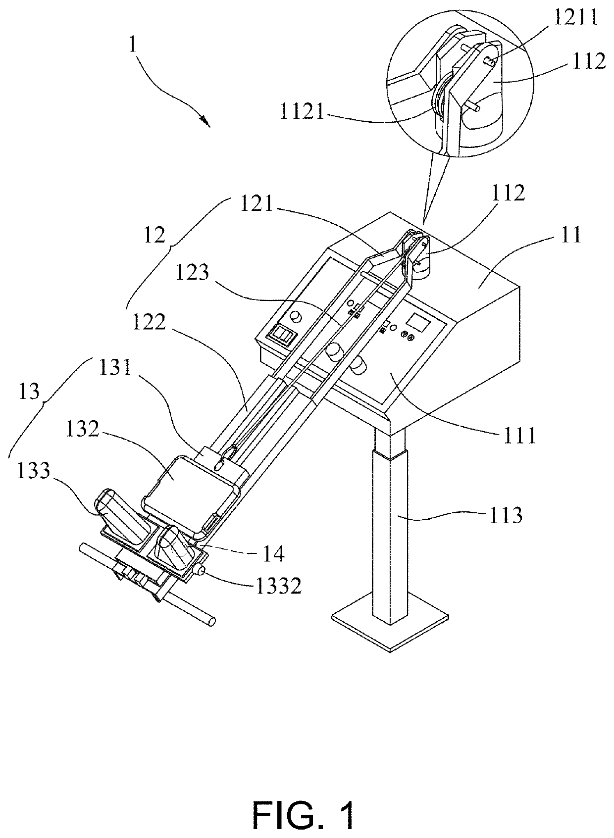
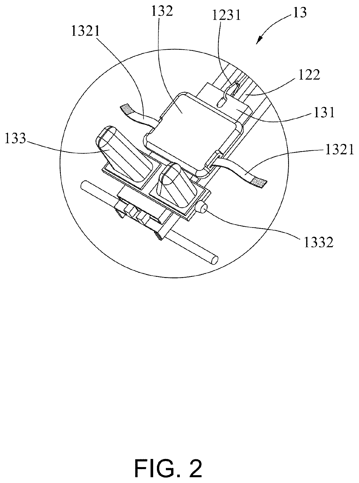
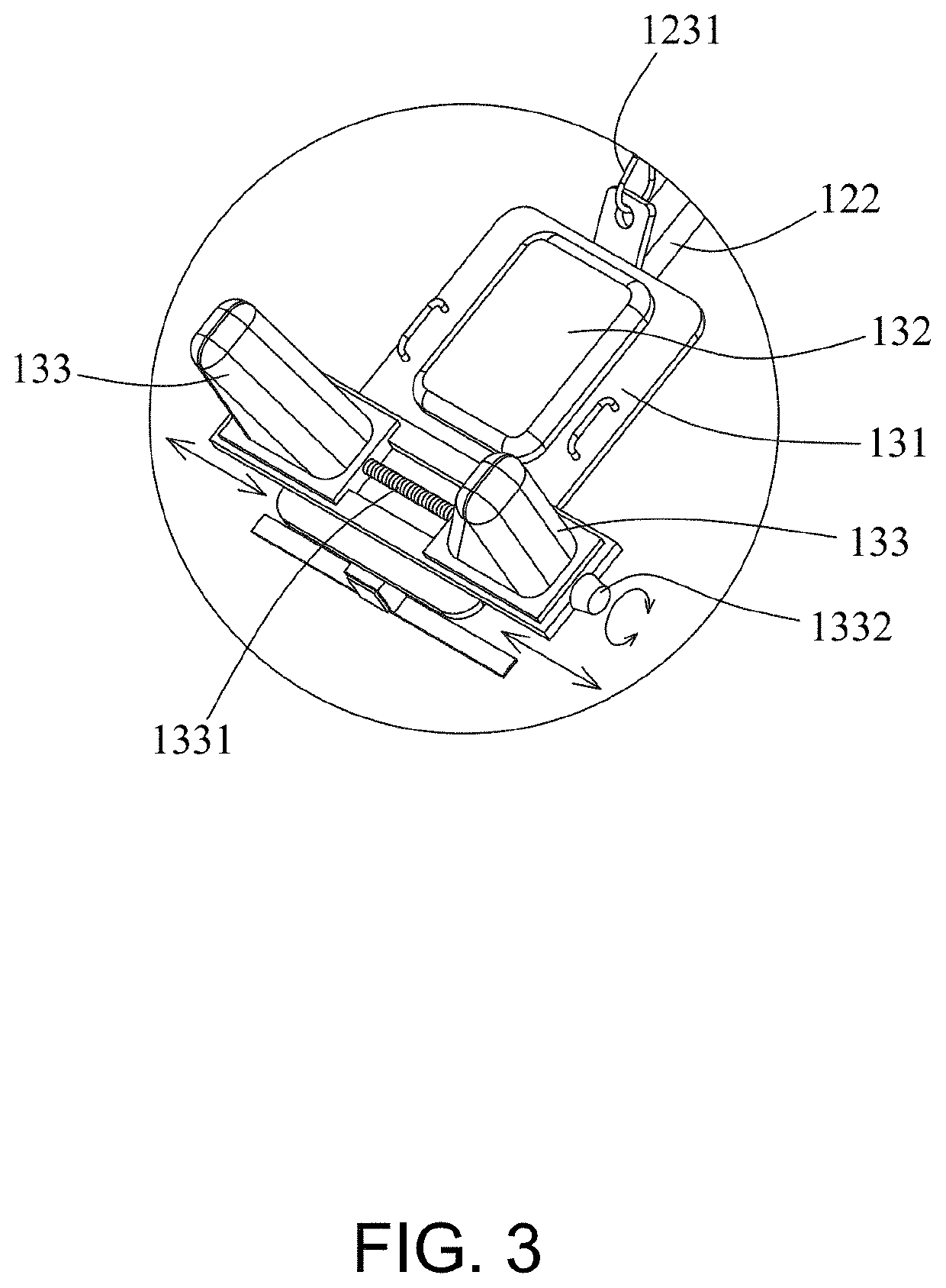
[0035]In the present disclosure, the cervical spine traction device, equipment and method mainly utilizes the program code built in the main controller (11) to calculate the optimal traction data according to the weight and height of the user (3) lying down on the platform (2), wherein the traction data comprises the cervical spine stretching force, distance and time. Further, by sensing the temperature of the neck of the user (3) and massaging the neck, the tension force of the neck muscle can be relaxed, the tightness of the user (3) can be sufficiently eliminated, and the cervical spine of the user (3) is corrected. Firstly, referring to FIG. 1, FIG. 1 is a schematic diagram showing a whole structure of a cervical spine traction device according to one embodiment of the present disclosure, and the cervical spine traction device (1) at least comprises a main controller (11), a fixing unit (12), a movable unit (13) and thermal massage units (14).

[0036]The main controller (11) at le...


PUM


Abstract

The present disclosure relates to a cervical spine traction device, equipment and method, wherein a built-in program code determines a cervical spine stretching force according to a sensed weight of a user. The cervical spine traction device has a main controller, a fixing unit, a movable unit and thermal massage units. By storing the program code in the main controller, the optimal traction data comprising a cervical spine stretching distance, the cervical spine stretching force and a cervical spine stretching time can be calculated according to the weight and height of the user lying down on the platform. Further, by sensing the temperature of the neck of the user and massaging the neck, the tension force of the neck muscle can be relaxed, the tightness of the user can be sufficiently eliminated, and the cervical spine of the user is corrected.

Description

BACKGROUNDTechnical Field[0001]The present disclosure relates to a cervical spine traction device, equipment and method, and in particular, to a cervical spine traction device, equipment and method, which built-in program code can determine a traction data according a sensed weight of a user.Related Art[0002]In a busy and tense modern society, the tempo with which people work and live is fast, so that the pressure is increasing, and the time to relax is less. Thus, the proportion which the patients have degenerative diseases or injuries in cervical spines is higher. The patients having degenerative diseases or injuries in cervical spines usually work the desk for a long time, and their cervical spines maintains a in a specific state for a long time, which causes the neck muscles to be in a non-coordinated stress state for a long time, such that the muscles and ligaments in the back of the neck may be damaged or degenerative.[0003]The traction can be used for rehabilitation of all jo...

Claims


Application Information

Patent Timeline
Patent Type & Authority Applications(United States)
IPC IPC(8): A61H1/02A47G9/10
CPCA61H1/0296A47G9/1081A47G9/1036A61H2201/02A61H2201/5007A61H2201/1607A61H2230/80A61H2205/04A61H2201/1215A61H2201/5023A61H2230/50A61H1/0222A61H2201/1664A61H2201/0192A61H2203/0456A61H2201/0207A61H2201/1611A61H2201/0142A61H2201/149A61H2201/5043A61H2230/82
Inventor CHANG, HOLI, WEI LEE
Owner NAT TAIPEI UNIV OF TECH
Learn More