
Linear motor

A linear motor and coil technology, applied in the direction of electric components, electrical components, electromechanical devices, etc., can solve the problems of uneven speed, difficult cooling, complex cooling structure, etc., and achieve the effect of high utilization efficiency, strong mechanical strength, and simple structure

Inactive Publication Date: 2003-07-30
CHRONOFANG
View PDF0 Cites 2 Cited by
  • Summary
  • Abstract
  • Description
  • Claims
  • Application Information

AI Technical Summary

Problems solved by technology

[0007] The second problem is that although the movable coil part 103 generates a lot of heat, it is difficult to cool it due to its movement, and because it must occupy a large space, it must have a complicated cooling structure in order to realize it.
If the heat generation problem of the movable coil part 103 is not solved, the peripheral temperature of the movable coil part 103 will rise, and for example, deformations such as outward warpage and expansion of the transported body such as a semiconductor wafer mounted on the stage will occur, and it will be difficult to maintain the The accuracy of the conveying body will have a bad influence
[0008] The third problem is that in the type shown in FIG. 14, since the coils of the movable coil part 103 are cylindrical or rectangular, the permanent magnets are only set on two sides facing each other, so the thrust generation is effective. less flux
If the excitation current of the movable coil part 103 is increased in order to increase the thrust force, it will be more difficult to solve the above-mentioned second problem.
[0009] As a fourth problem, especially in the planar facing type (flat type) linear motor, a plurality of plate-shaped permanent magnets are arranged on the side of the stator, and a plurality of plate-shaped permanent magnets are arranged on the side of the movable element facing it. Coil, at this time, because the permanent magnet and the coil are arranged in a segment structure interrupted therebetween, when the mover moves in the axial direction, there must be regular and continuous phenomena in which the yoke and the permanent magnet attract each other and the positions where they do not attract each other (uneven speed)

Method used


Image

  • Linear motor
  • Linear motor
  • Linear motor

Examples


Embodiment Construction

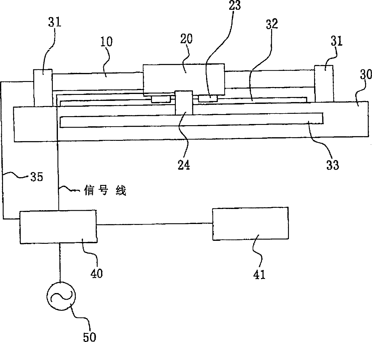
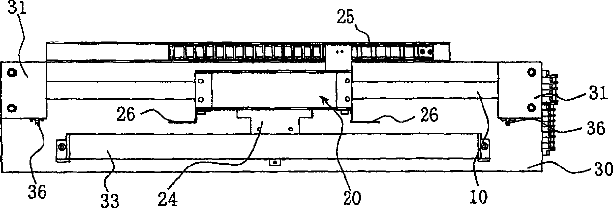
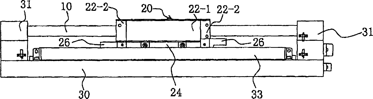
[0097] Hereinafter, the linear motor according to the first embodiment of the present invention will be described. Fig. 1 shows a schematic configuration of a linear motor, and Figs. 2a to 2d are diagrams of the linear motor viewed from four directions. That is, Fig. 2a is a plan view, Fig. 2b is a side view seen from the lower side of Fig. 2a, Fig. 2c is a side view seen from the upper side of Fig. 2a, and Fig. 2d is a view seen from the right side of Fig. 2a.

[0098] In Figs. 1, 2a to 2d, the linear motor includes: a shaft body (hereinafter referred to as a stator) 10 that houses a plurality of electromagnet coils (hereinafter referred to as coils) arranged in a row; A movable magnet body (hereinafter referred to as a mover) 20 that can move in the same direction as the extending direction of the stator 10 through the interaction. The stator 10 is installed between two brackets 31 fixed to the base 30 at a certain interval.

[0099] 3a and 3b again, the internal structure of th...


PUM


Abstract

The present invention provided a linear motor, of which the problem of heat from a movable part can be solved. In the linear motor, a plurality of electromagnet coils are arranged in series and permanent magnets are arranged in combination with the electromagnetic coils so that the permanent magnets interact with the magnetic flux from the electromagnetic coils to travel. The magnetic coils comprise a coil 12 of U phase, V phase, and W phase, each connected in star connection, which are mounted around a center core 11 of hollow-shaped axis in series to cover the whole length of the traveling range of the permanent magnets in such a way that the magnetic pole axis of each magnetic coil is in the same direction with that of the axial core of the center core. The permanent coils form a cylindrical shape to surround the electro magnetic coils and comprises a plurality of permanent magnets 21, each having the length three times that of the coil of respective phase in terms of the magnetic pole axis, wherein adjacent each magnetic poles are opposed to each other and whole permanent magnets are arranged in series so that their magnet pole axis is in the same direction as that of the axial core of the center core.

Description

Technical field [0001] The present invention relates to linear motors. Background technique [0002] There are various types of linear motors. If it is not the case that requires a strong driving force like a linear motor drives a vehicle, most of them are composed of a combination of permanent magnets and electromagnet coils. Such a linear motor composed of a combination of a permanent magnet and an electromagnet coil can be considered as a driving source of a precision micro-level or a precision positioning level in the field of semiconductor manufacturing equipment, for example. This is because the linear motor drive mechanism has not only high driving speed, but also high positioning accuracy, high repeat positioning accuracy, overshoot and undershoot that occur during driving and stopping, compared to the conventional ball-head bolt drive mechanism. The advantages of relatively small and small speed fluctuations when moving at a constant spee...

Claims


Application Information

Patent Timeline
Patent Type & Authority Applications(China)
IPC IPC(8): H02K41/03
CPCH02K41/03
Inventor 渡边浩司
Owner CHRONOFANG
Learn More