
Field-sequential liquid crystal display device and driving method

A liquid crystal display device and technology of the display device, which are applied to static indicators, instruments, etc., can solve the problems of increased power consumption and increased cost, and achieve the effects of simplifying the structure, reducing EMI, and reducing signal loss

Inactive Publication Date: 2003-07-09
ORTUS TECH
View PDF0 Cites 21 Cited by
  • Summary
  • Abstract
  • Description
  • Claims
  • Application Information

AI Technical Summary

Problems solved by technology

[0009] Therefore, in addition to the module circuit 14, a plurality of external electronic components such as the image sending circuit 11 are required, thereby increasing the power consumption of the entire system and increasing the cost related to manufacturing.

Method used

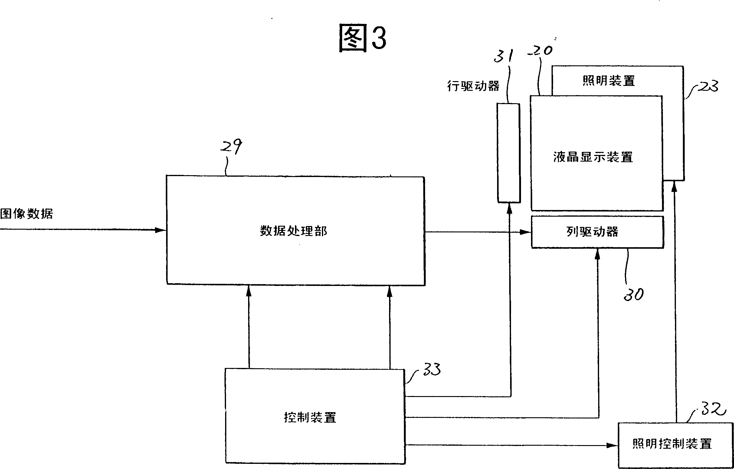

Image

  • Field-sequential liquid crystal display device and driving method
  • Field-sequential liquid crystal display device and driving method
  • Field-sequential liquid crystal display device and driving method

Examples


Embodiment Construction

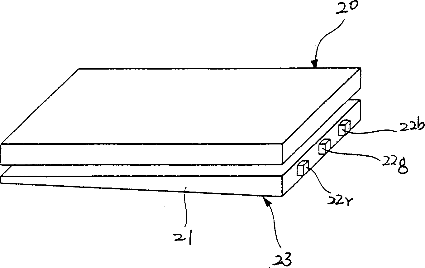
[0033] The present invention is a field sequential liquid crystal display device, such as figure 1 As shown, there are a plurality of pixels arranged in a matrix, with a liquid crystal display element 20, a light guide plate 21, and light sources 22r, 22g, and 22b of various colors, which are composed of an illumination device 23; the above-mentioned liquid crystal display element 20 corresponds to the voltage applied to the electrodes of each pixel To control the light transmission of the pixel, it is an active matrix type and uniformly aligned; the light guide plate 21 is arranged on the side opposite to the viewing side of the liquid crystal display element 20; the color light sources 22r, 22g, and 22b are arranged on One end of the light guide plate 21 emits lights of red R, blue G, and green B; The light is uniformly guided to the entire surface of the liquid crystal display element 20 to irradiate the above-mentioned liquid crystal display element 20 .

[0034] figur...


PUM


Abstract

A liquid crystal display device incorporates, within the same integrated circuit, a plurality of memories which store R, G, and B data supplied in parallel from an image source for the respective color components, a multiplexer which serially reads out the R, G, and B data stored in these memories and supplies them to the liquid crystal display unit, a mode switch, a D / A converter, and a buffer amplifier.

Description

technical field [0001] The present invention relates to a field sequential liquid crystal display device and a driving method thereof. Background technique [0002] As a liquid crystal display device for displaying a color image, a liquid crystal display device of a type that has a liquid crystal element sandwiching a liquid crystal between a pair of substrates on which electrodes are respectively formed on opposing inner surfaces is being studied, and It has: a liquid crystal display element, which controls the transmission of light to display images; a backlight (back light), which is arranged behind the liquid crystal display device, and emits light of various colors to the liquid crystal display element according to a predetermined period; a control device , which controls writing of display data corresponding to one of the plurality of colors toward the liquid crystal display element and writing of the color corresponding to the display data from the backlight in each s...

Claims


Application Information

Patent Timeline
Patent Type & Authority Applications(China)
IPC IPC(8): G02F1/133G09G3/20G09G3/34G09G3/36
CPCG09G3/3406G09G2310/0235G09G3/3611G09G3/36
Inventor 山内慎吾
Owner ORTUS TECH
Learn More