
Automatic cooker

A technology of automatic cooking and power motor, which is applied in the field of kitchen utensils, can solve problems such as oil fume pollution, cumbersome cooking methods, and hard work, and achieve the effect of improving the environment

Inactive Publication Date: 2003-07-02
苏福生
View PDF0 Cites 11 Cited by
  • Summary
  • Abstract
  • Description
  • Claims
  • Application Information

AI Technical Summary

Problems solved by technology

In addition, the cook cannot leave the stove during the cooking process, and the cooking process will cause high temperature and oily smoke pollution in the kitchen, and the environment is very bad
This traditional cooking method is very tedious and laborious.
The existing treatment method is to discharge the lampblack from the indoor to the outdoor through the range hood, which pollutes both the indoor and the outdoor

Method used


Image

  • Automatic cooker
  • Automatic cooker
  • Automatic cooker

Examples


Embodiment Construction

[0022] Specific embodiments of the present invention will be described in detail below in conjunction with the accompanying drawings.

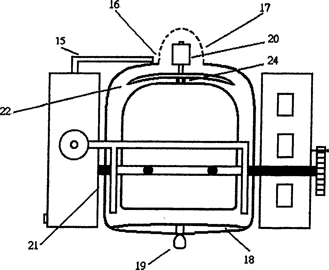
[0023] Figure 1, figure 2 As shown, the automatic cooking machine of the present invention is formed after a power part motor 20 is connected with the pot body 2 . Food (solid or liquid) stirring rib 7 is arranged in the pot body 2. By putting a hollow hemispherical food container or pot body 2 in the circle bearing ring 6 of a bearing structure, when the positioning eye 24 at the bottom of the pot body 2 is connected with the positioning post of the motor 20, the pot body 2 will be positioned at the position of the motor 20. Driven so that it can turn in the weft direction (see when the pot body is vertical Figure 4 ), the rotation can be one-way or two-way, can be continuous or intermittent, can be warp or weft, can be greater or less than 360 degrees. There are two meridional rotating shafts 21 on the outer ring 6 of the bearing structu...


PUM


Abstract

An automatic electric cooker is composed of a semi-spherical hollow pot body able to rotate in both latitudinal and longitudinal directions under drive of a motor, a stirrer in the pot, an electric heater, a casing for containing the pot body and the electric heater, an automatic controller, and a soot exhauster.

Description

technical field [0001] The invention relates to kitchen utensils, in particular to an electric automatic cooking machine. Background technique [0002] The traditional way of cooking is that the cook must operate with two hands at the same time. That is, hold the spatula in one hand and hold the pot body in the other hand. More importantly, in order to heat the food evenly to an appropriate level, the hand holding the spatula must stir constantly in the pot. In addition, the cook cannot leave the stove during the cooking process, and the high temperature and oil fume pollution in the kitchen will be caused during the cooking process, and the environment is very bad. This traditional cooking method is very tedious and laborious. The existing treatment method is to discharge the lampblack from the indoor to the outdoor through the range hood, which pollutes both the indoor and the outdoor. Contents of the invention [0003] The purpose of the present invention is to over...

Claims


Application Information

Patent Timeline
Patent Type & Authority Applications(China)
IPC IPC(8): A47J27/00A47J37/04A47J37/06F24C7/00F24C15/20
CPCA47J27/004A47J37/047A47J37/0623A47J37/0629F24C7/00F24C15/2042
Inventor 苏福生
Owner 苏福生
Learn More