
Temp.-compensation type crystal oscillator and method for regulating its out-put frequency

A technology for crystal oscillators and temperature compensation, applied in power oscillators, output stability, electrical components, etc., can solve problems such as increasing size and difficulty in miniaturizing mobile communication terminals

Inactive Publication Date: 2003-06-11
SAMSUNG ELECTRO MECHANICS CO LTD
View PDF0 Cites 0 Cited by
  • Summary
  • Abstract
  • Description
  • Claims
  • Application Information

AI Technical Summary

Problems solved by technology

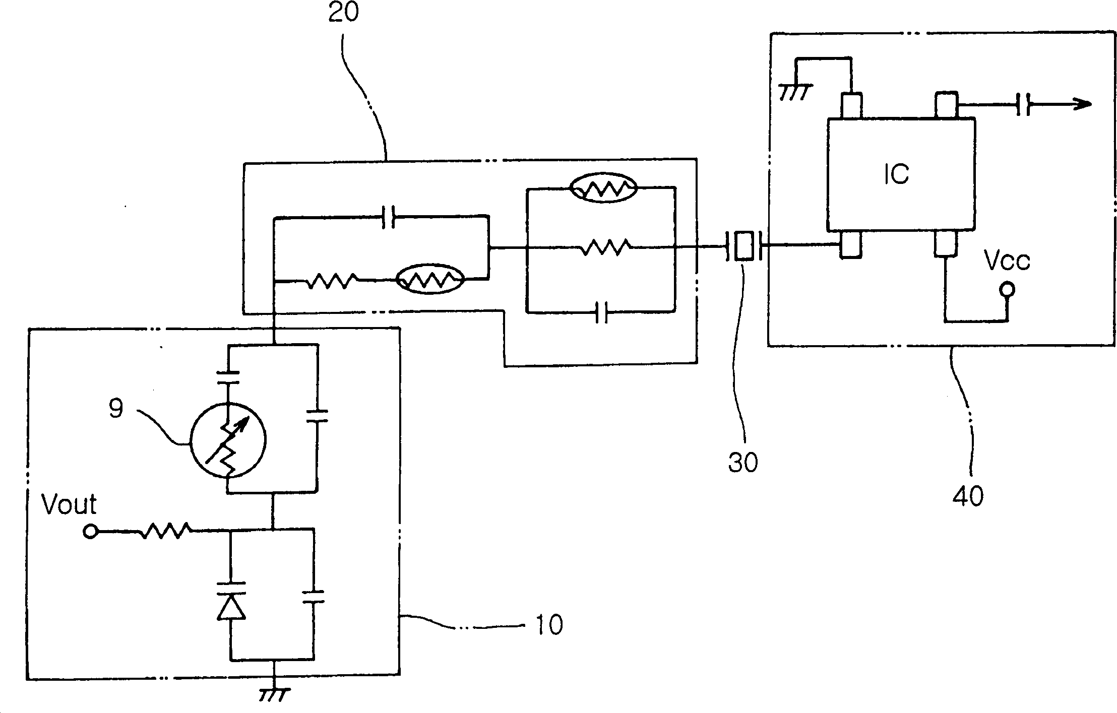
[0006] However, the size of the trimmable chip resistors used in the conventional temperature compensated crystal oscillator of Fig. 2 is several square millimeters, so the same size as the 2 or 4.7×2.9mm 2 Trimmable chip resistors require considerably larger mounting area compared to crystal oscillators
Therefore, the size of the trimmable chip resistor increases the size of the final product, making miniaturization suitable for mobile communication terminals difficult

Method used


Image

  • Temp.-compensation type crystal oscillator and method for regulating its out-put frequency
  • Temp.-compensation type crystal oscillator and method for regulating its out-put frequency
  • Temp.-compensation type crystal oscillator and method for regulating its out-put frequency

Examples


Embodiment Construction

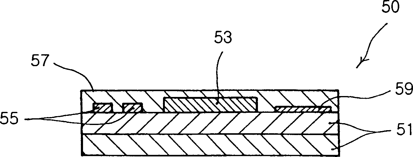
[0026] image 3 is a side sectional view of a temperature compensated crystal oscillator 100 according to a preferred embodiment of the present invention;

[0027] refer to image 3 The temperature compensated crystal oscillator 100 includes a top layer 101, on which a crystal oscillator unit 103 and components 105 constituting a temperature compensation circuit and an oscillator circuit are printed with conductive patterns. Here, the crystal oscillating unit 103 includes a crystal oscillating plate to generate an output frequency. The layered structure 101 consists of three layers 101a, 101b and 101c. In addition, the upper surface of the first layer 101 a on which the crystal oscillation unit 103 and the circuit components 105 are mounted is covered with a metal case 107 .

[0028] Such as image 3 As shown, the feature of the present invention is that the planar thin film resistor 109 is formed on the upper surface of the third layer 101c, and the third layer 101c is al...


PUM


Abstract

Disclosed herein is a temperature compensated crystal oscillator and method for adjusting an output frequency thereof. The temperature compensated crystal oscillator has a crystal oscillating unit and at least one part for temperature compensation and oscillation circuits. The temperature compensated crystal oscillator has a layered structure and a planar thin film resistor. The layered structure has an upper layer on which the crystal oscillator and the part are mounted, and at least one layer on which conduction patterns fare formed. The planar thin film resistor is arranged on an upper surface of a bottom layer of the layered structure so as to adjust an output frequency of the temperature compensated crystal oscillator. Therefore, an area occupied by a resistor for adjusting an output frequency can be minimized by inserting a resistor for adjusting an output frequency between layers, thus miniaturizing products.

Description

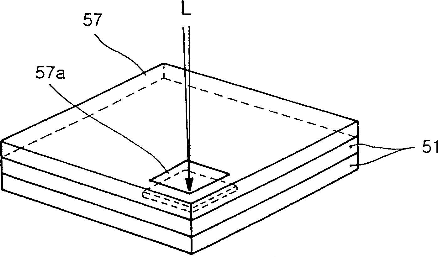
technical field [0001] The present invention generally relates to a temperature-compensated crystal oscillator that facilitates adjustment of the output frequency, and more particularly to a temperature-compensated crystal oscillator and a method of adjusting its output power by inserting a thin film between the layers of its layered structure The output power of this temperature-compensated crystal oscillator is adjusted by fine-tuning the thin-film resistor with the underlying laser beam. Background technique [0002] A crystal oscillator using a crystal oscillating plate is a necessary component to generate an oscillation frequency to control the transmission and reception of signals between mobile communication terminals. Crystal oscillators have excellent frequency stability compared to other oscillators. The commonly used crystal oscillator is a temperature compensated crystal oscillator (TCXO), which can solve the problem that the oscillation frequency changes with t...

Claims


Application Information

Patent Timeline
IPC IPC(8): H03B5/32H03B5/04H03L1/02
CPCH03L1/028H03B5/32
Inventor 郑哲泳
Owner SAMSUNG ELECTRO MECHANICS CO LTD
Learn More