Backflush filter, in particular for filtering lubricant oil

A countercurrent washing and filter technology, which is applied to the installation/connection of fixed filter element filters, membrane filters, lubricant purification devices, etc., and can solve the problem of large loss of filtrate

Inactive Publication Date: 2003-06-04
BOLL & KIRCH FILTERBAU
View PDF2 Cites 6 Cited by
  • Summary
  • Abstract
  • Description
  • Claims
  • Application Information

AI Technical Summary

Problems solved by technology

Large filtrate loss during countercurrent washing

Method used


Image

  • Backflush filter, in particular for filtering lubricant oil
  • Backflush filter, in particular for filtering lubricant oil
  • Backflush filter, in particular for filtering lubricant oil

Examples


Embodiment Construction

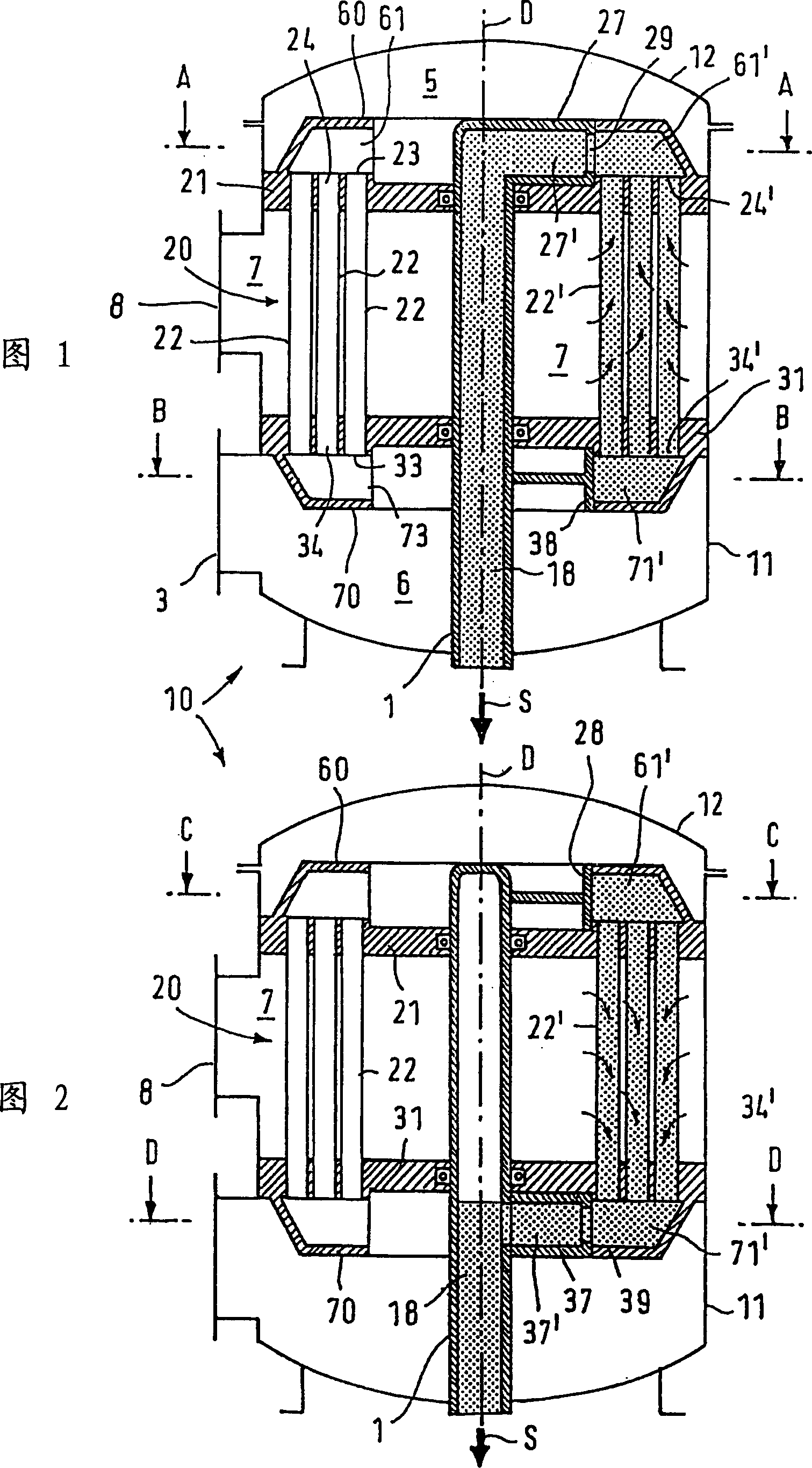
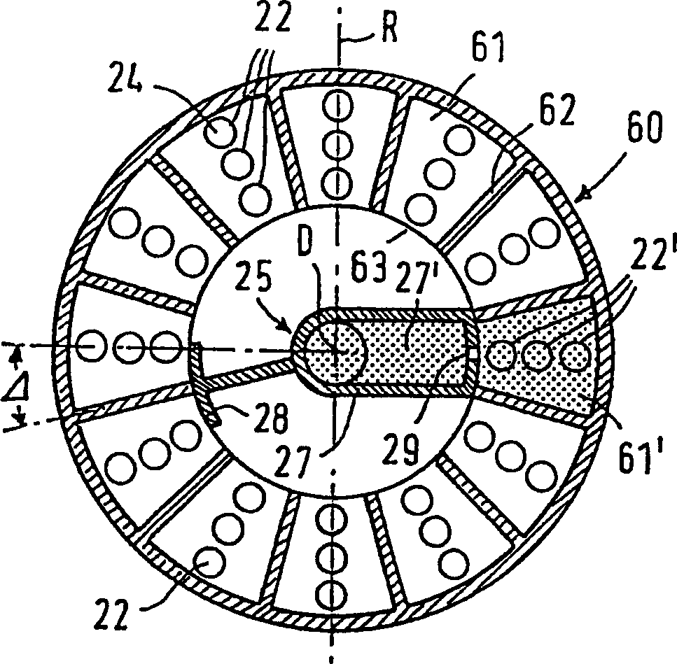
[0019] 1 and 2 are schematic diagrams of a backwash filter, which includes a filter housing 11 and a housing cover 12 . The filter insert 20 is arranged in the inner space of the filter housing 11 and the housing cover 12 and comprises a plurality of filter parts 22, 22' placed concentrically around the axis of rotation D of the filter. As will be explained below, the filter element 22 performs filtering and the filter element 22' performs backwashing. The filter parts 22, 22' are clamped between the upper perforated plate 21 and the lower perforated plate 31, so that during the filtering operation, the oil sludge to be filtered that enters the backwashing filter 10 through the filter inlet 3 flows into the filter element 22. In the upper inflow end 24 and the lower inflow end 34 . The sludge flows from the inside through the filter wall of the filter element 22 to the outside and enters the filter chamber 7 as filtrate. The filtrate comes out of the filter cavity and is sen...


PUM


Abstract

A backflushing filter for filtering oil includes filter candles 22 which are open at both ends 24, 34 and disposed around a rotary shaft 1 in a filter housing. A cleaning device is moved in conjunction with the rotary shaft and includes upper and lower flushing cocks communicating with an outflow valve via the shaft for cleaning the candles during a backflushing operation. The upper flushing cock 27 is offset by an angle in the direction of rotation in relation to the lower flushing cock 37. A lower closure element 38 moves in conjunction with the upper flushing cock at the opposite end of a filter candle(s) selected for backflushing. Likewise, an upper closure element is associated with the lower flushing cock. The candles can be reverse-flushed in opposite directions and at different times by the flushing cocks and closure elements. The flushing cocks and closure elements are moved inside annular deflection hoods 60, 70.

Description

technical field [0001] The invention relates to a backwashing filter, especially a backwashing filter for filtering lubricating oil and fuel oil. Background technique [0002] Reversible flow filters are preferably used for filtering fuel and lubricating oils of machines, engines, marine engines and the like. In a corresponding backwash filter, the filter element is placed in the filter housing around the filter axis, while the sludge to be cleaned flows into the interior of the filter element via an open inflow. Part of this liquid flow flows as filtrate through the filter element wall into the filter space and from there to the filter outlet. In order to discharge the dirt particles deposited on the inner surface of the filter element into the discharge line, there is a cleaning device which ensures the continuous operation of the backwash filter. The cleaning device rotates from one element to the other using a rotary shaft placed on the centerline of the filter. The o...

Claims


Application Information

Patent Timeline
Patent Type & Authority Applications(China)
IPC IPC(8): F01M11/03B01D29/11B01D29/50B01D29/60B01D29/66B01D35/02B01D35/16F02M37/22
CPCB01D29/117B01D2201/0453B01D29/52B01D29/668B01D29/902B01D29/11B01D29/54B01D29/66
Inventor 威利·罗特威廉·维滕海因茨·辛多尔夫鲁迪格·伦纳兹西瓦格纳纳姆·坎迪亚
Owner BOLL & KIRCH FILTERBAU
Why Eureka
Try Eureka