Scraper for piston rod of reciprocating compressor

A technology of scraping device and piston rod, which is applied in the direction of engine sealing, liquid variable displacement machinery, mechanical equipment, etc., and can solve the problems of scraper ring wear, oil scraping function deterioration and oil leakage hazards, etc.

Inactive Publication Date: 2003-05-14
NUOVO PIGNONE TECH SRL
View PDF0 Cites 13 Cited by
  • Summary
  • Abstract
  • Description
  • Claims
  • Application Information

AI Technical Summary

Problems solved by technology

The movement of the piston rod causes mechanical stresses in the radial direction, to which the wiper ring is exposed, which contributes to rapid wear of the wiper ring, with the result that the oil wiper function deteriorates and thus leads to a hazardous oil leakage hazard

Method used


Image

  • Scraper for piston rod of reciprocating compressor
  • Scraper for piston rod of reciprocating compressor
  • Scraper for piston rod of reciprocating compressor

Examples


Embodiment Construction

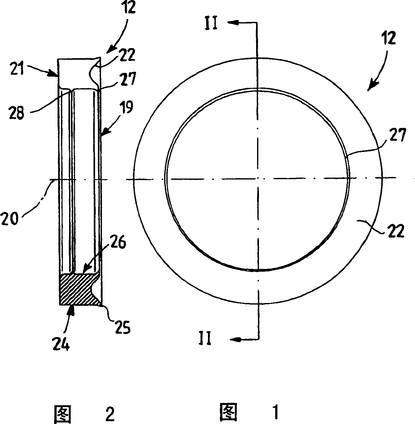
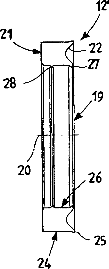
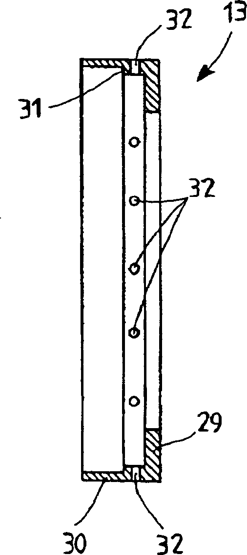
[0033] The scraping device shown in these figures is indicated generally at 10 and is mounted on the piston rod 11 of the reciprocating compressor. The scraper device 10 which is the subject of the invention comprises a scraper ring 12 and a box 13 which houses the scraper ring 12 and centers it on the piston rod 11 .

[0034] The scraper device 10 is shown in Figure 5 Fitted in a corresponding seat on the inner diameter of the support element 14 and in a transverse receiving element 16 clamped together by tie rods 15 . These supporting elements 14 and receiving elements 16 form the housing separating the crank mechanism and the compression chamber, neither of which is shown in this figure, which schematically shows a possible assembly.

[0035] The side facing the compression chamber is downstream of the scraping means, where there is no longer any lubricating oil, and a sealing means 17 is also provided. The sealing device 17 includes a corresponding sealing member, which...


PUM


Abstract

A scraper device (10) for a reciprocating compressor piston rod (11) comprises at least one scraper ring (12), provided with at least one lip which faces the surface of the said rod (11), and a box (13) to contain the scraper ring (12) and for centring on the rod (11), wherein this scraper ring (12) is produced by means of mechanical processing of deformable plastics materials and wherein this container box (13) is accommodated in support elements (14) with radial play (34).

Description

technical field [0001] The invention relates to a scraper device for a piston rod of a reciprocating compressor. Background technique [0002] A conventional reciprocating compressor includes one or more cylinders in which reciprocating sliding pistons are mounted. [0003] As far as the kinematic control mechanism for the reciprocating movement of the piston is concerned, mention is made by way of example of the kinematic mechanism comprising a connecting rod and crank or connecting rod, crank and crosshead. [0004] The second proposed form of transmission of reciprocating motion is used in machines which, instead of directly connecting the foot of the piston rod to the piston, require the insertion of a rod or piston rod. [0005] However, the rod is not designed to withstand lateral forces, but is guided along its straight movement by a so-called crosshead that forces the center of the connection between the piston rod and the foot of the connecting rod along the cylind...

Claims


Application Information

Patent Timeline
IPC IPC(8): F04B39/00F04B39/04F16J15/18
CPCF04B39/041
Inventor F·格拉齐亚尼M·伊尔科贝利S·普拉特斯
Owner NUOVO PIGNONE TECH SRL
Why Eureka
Try Eureka