
Paper sheet transfer appts. and image forming appts.

A paper conveying and image technology, which is applied in image communication, transportation and packaging, electrical recording technology using charge graphics, etc., can solve the problems of rising production costs and large-scale devices

Inactive Publication Date: 2003-05-07
CANON KK
View PDF0 Cites 59 Cited by
  • Summary
  • Abstract
  • Description
  • Claims
  • Application Information

AI Technical Summary

Problems solved by technology

[0006] In the structure of this second conventional example, contrary to the above-mentioned first conventional example, since the discharge roller and the reverse roller 106 are separated, the productivity during double-sided recording can be improved, but there are rollers and reverse conveying paths. There must be a margin, so there is a problem of increasing the size of the device while increasing the production cost
[0007] However, in any case, as a double-sided configuration of the image forming apparatus, the user can only choose one side.

Method used


Image

  • Paper sheet transfer appts. and image forming appts.
  • Paper sheet transfer appts. and image forming appts.
  • Paper sheet transfer appts. and image forming appts.

Examples


Embodiment approach 1

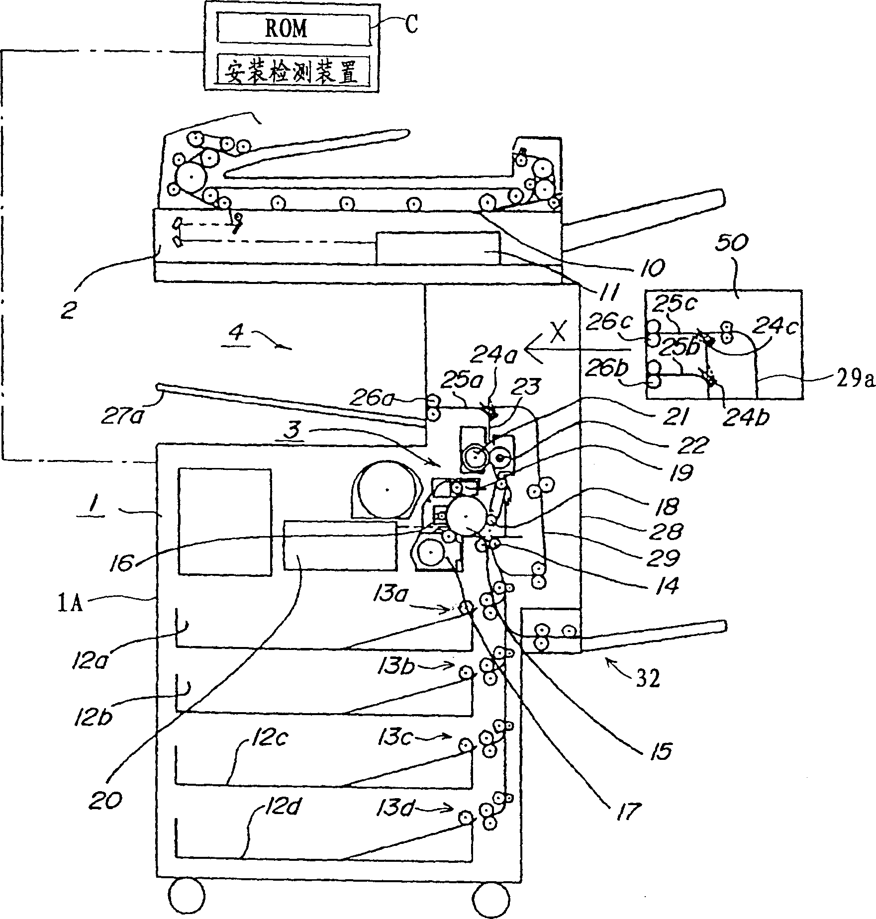
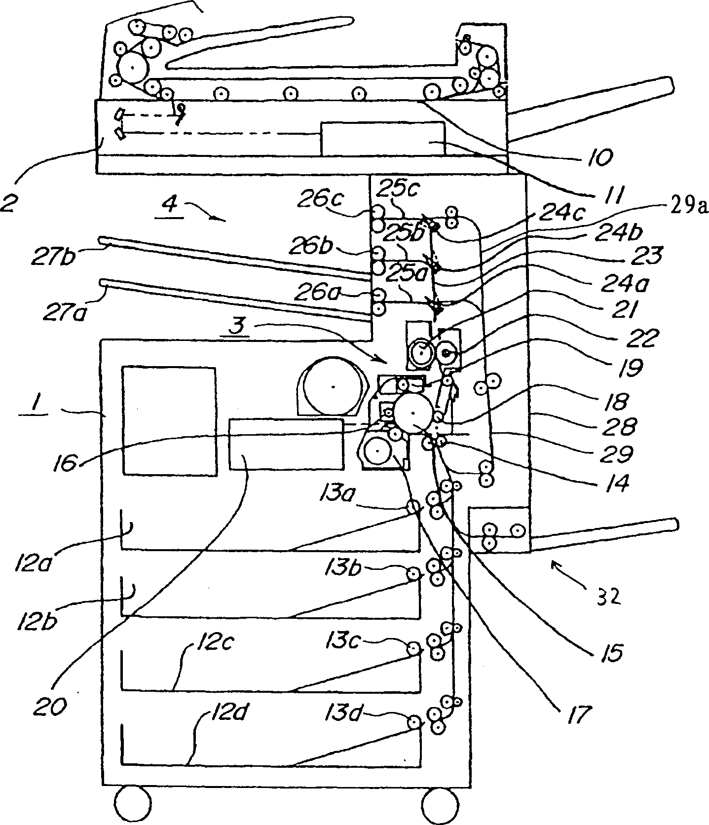
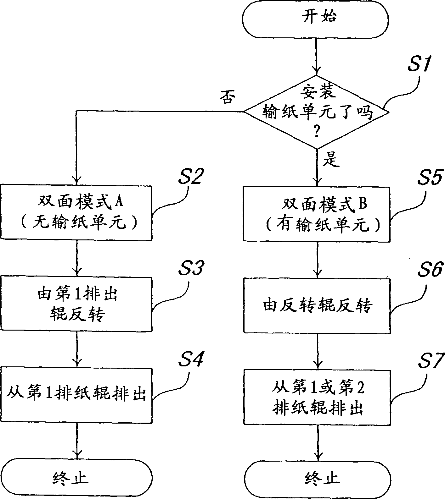
[0027] Embodiment 1 of a paper conveying device and an image forming apparatus according to the present invention will be described below using the drawings. figure 1 is an overall configuration diagram of the image forming apparatus showing the state before the conveyance unit is installed, figure 2 is an overall configuration diagram of an image forming apparatus showing a state in which a transport unit is installed, image 3 To illustrate the flow chart of the double-sided recording operation with or without the transport unit of the present invention, Figure 4 For a diagram illustrating the operation of double-sided recording, Figure 5 A diagram illustrating the movement of paper.

[0028] figure 1 In the image forming apparatus 1 shown, an image reading unit 2 is provided on an upper portion of an apparatus body 1A. The above-mentioned image reading unit 2 has an original glass table 10 on which an original is placed and a CCD sensor 11 as an image reading devic...

Embodiment approach 2

[0054] Embodiment 2 of the paper conveying device and image forming apparatus of the present invention will be described below using the drawings. Figure 6 The image forming apparatus according to this embodiment is an overall configuration diagram showing a state in which the transport unit is mounted, and the same reference numerals are assigned to configurations that overlap with those described in Embodiment 1, and their descriptions are omitted.

[0055] In the first embodiment described above, it is assumed that the transport unit 50 can be attached above the first paper discharge roller 26 a in the paper discharge unit 4 . On the other hand, in this embodiment, the conveyance unit which has a 2nd inverting device is attached to the side of an apparatus.

[0056] shown in Figure 6 The dotted line part of is the conveyance unit 51, which has the reversing roller 30 and the reversing path 31 as the 2nd reversing means. When double-sided recording is performed using suc...


PUM


Abstract

A sheet conveying apparatus and an image forming apparatus of the present invention enable a user himself or herself to select a plurality of double-sided recording modes by use of one common image forming apparatus. Each of the sheet conveying apparatus and the image forming apparatus includes a first reversing member, provided in an apparatus main body, for reversing a sheet on which an image is recorded by an image forming unit, a conveying unit including a second reversing member for reversing the sheet on which the image is recorded by the image forming unit, and so provided as detachably attachable to the apparatus main body, and a double-sided conveying portion for conveying the reversed sheet again to the image forming unit in order to perform double-sided recording.

Description

technical field [0001] The present invention relates to an image forming apparatus such as a copying machine, and particularly relates to an apparatus capable of improving productivity for recording on both sides. Background technique [0002] In recent years, image forming apparatuses such as copiers have widely adopted a configuration in which a paper discharge unit is provided in a space formed in the device body (hereinafter referred to as in-machine paper discharge) following digitization. At the same time, the conveyance of the paper sent from the paper feeder arranged on the lower side of the device body is approximately vertical, and the length of the conveyance path is shortened by recording the image on the paper between the paper discharge unit arranged above and The time to achieve fast copying (forming the first image) is shortened. In this case, in order to improve the productivity of double-sided recording, the current method is to increase the conveying spee...

Claims


Application Information

Patent Timeline
IPC IPC(8): G03G15/00B65H29/58B65H29/60B65H85/00G03G15/23H04N1/00
CPCG03G15/234
Inventor 三宅博章
Owner CANON KK
Learn More