
Combustion turbine with axial relative movel guide unit

A technology for gas turbines and guiding parts, which is applied in the directions of gas turbine installations, engine components, machines/engines, etc., and can solve problems such as less favorable, large working blade tip clearance, disadvantage, etc.

Inactive Publication Date: 2002-11-27
SIEMENS AG
View PDF1 Cites 13 Cited by
  • Summary
  • Abstract
  • Description
  • Claims
  • Application Information

AI Technical Summary

Problems solved by technology

In other operating conditions, in the turbine of this design, the tip clearance of the working blades is relatively large, so this design is unfavorable
[0005] In another design known hitherto, although the relative movement between the components caused by heat can be made very small in many operating conditions by choosing a suitable material pairing, this design also makes it possible only in certain stable Optimum working blade tip clearance
The situation in other states is still less favorable

Method used


Image

  • Combustion turbine with axial relative movel guide unit
  • Combustion turbine with axial relative movel guide unit

Examples


Embodiment Construction

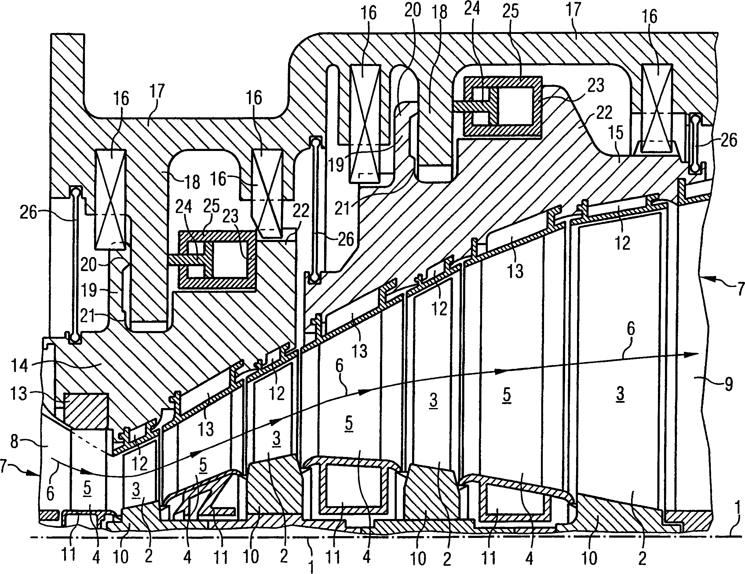
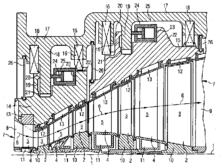
[0018] The rotor blade rings 2 are wedged on a turbine shaft 1 (not shown in detail), each rotor blade ring carrying a number of rotor blades 3 . The gas flow 6 guided by the guide vane ring 4 with several guide vanes 5 expands in the gas channel 7 and drives the rotor blades 3 .

[0019] The gas passage 7 has a circular cross-section, and its pressure side end is connected with a hot gas chamber 8. The compressed and heated gas flows out of the hot gas chamber 8 and flows along the direction of the arrow to reach the gas outlet hole 9. The radial inner boundary of the gas channel 7 is formed by the hub 10 of the rotor blade ring 2 wedged on the turbine shaft 1 and the non-rotatable hub 11 of the guide blade ring 4 supported by the inner ends of the guide vanes 5 . The gap between the hubs 10 and 11 is closed with a labyrinth seal.

[0020] The radially outer boundary of the gas channel 7 has a funnel-like cone shape and is formed by rings 12 and 13 . The rings 12 and 13 are...


PUM


Abstract

In order to balance different thermal expansions caused by thermal instability, the gas turbine of the present invention has a relatively movable guide part (14 / 15) in the axial direction, which surrounds a funnel-shaped gas channel (7) from the outside. In order to obtain an optimum working blade tip clearance, the invention proposes that at least one funnel-shaped guide part (14 / 15) can be moved axially controlled by a motor. By means of this axial movement, and due to the funnel-shaped configuration of the guide part, the width of the gap between the tips of the rotor blades can be varied.

Description

technical field [0001] The invention relates to a gas turbine having a guide vane ring and a working vane ring in a gas passage, a housing, and funnel-shaped guide members movable relative to each other but non-rotatable in the housing, the guide The part serves as a support for the rings forming an outer shroud for the gas channels. Background technique [0002] Gas turbines are constantly subjected to varying loads, not only during the start-up phase, but also during continuous operation. This can lead to unstable operation, especially with regard to the temperatures received by the components. In order to avoid damage to the turbine, the components are installed so that they can change size with heat without hindrance. [0003] In order to adequately minimize turbine losses due to transverse flow over the rotor blade tips, the radial gap between the rotor blade tips and the flow guide surface opposite thereto is kept as small as possible. Due to...

Claims


Application Information

Patent Timeline
IPC IPC(8): F01D11/08F01D11/22F01D25/24F02C7/28
CPCF01D11/22
Inventor 克里斯琴·肖尔茨彼得·蒂曼
Owner SIEMENS AG
Learn More