
Method for synchronizing timing output signal in digital communication equipment

A technology of clock output and synchronization processing, applied in digital transmission systems, synchronization devices, transmission systems, etc., to achieve the effect of ensuring continuity and smooth switching

Inactive Publication Date: 2002-10-30
EASTERN COMM
View PDF0 Cites 16 Cited by
  • Summary
  • Abstract
  • Description
  • Claims
  • Application Information

AI Technical Summary

Problems solved by technology

[0003] The technical problem to be solved by the present invention is to provide a simple and easy synchronous processing method for the clock output signal in digital communication equipment, so as to overcome the problem that the phase difference between the clock output signal and the clock output signal is always in a random state

Method used


Image

  • Method for synchronizing timing output signal in digital communication equipment
  • Method for synchronizing timing output signal in digital communication equipment
  • Method for synchronizing timing output signal in digital communication equipment

Examples


Embodiment Construction

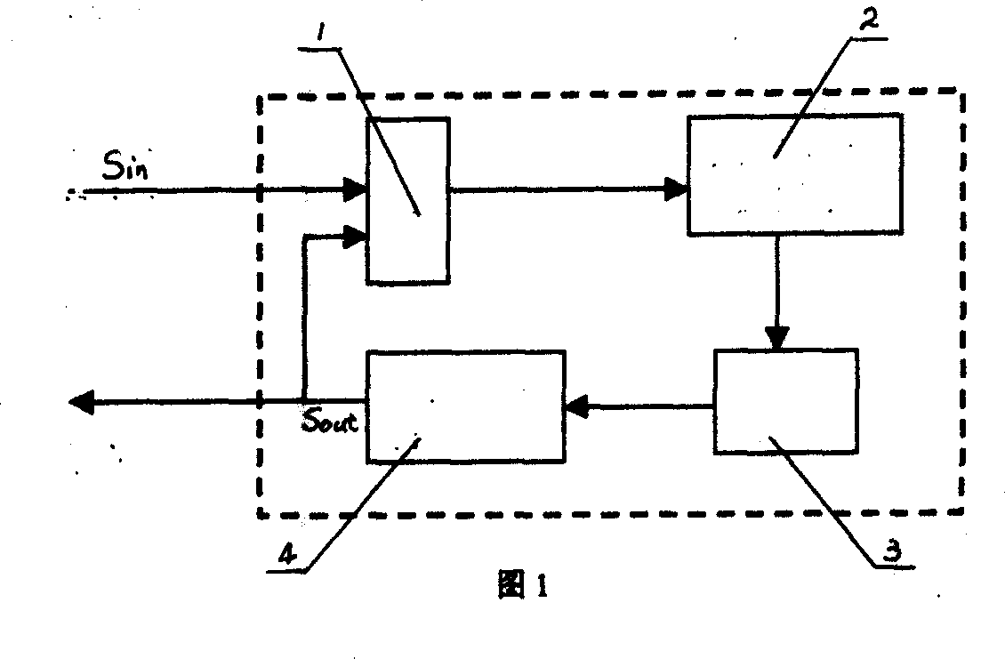
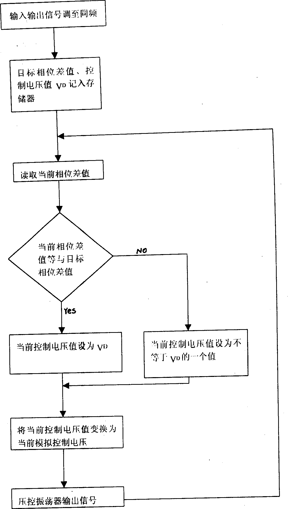
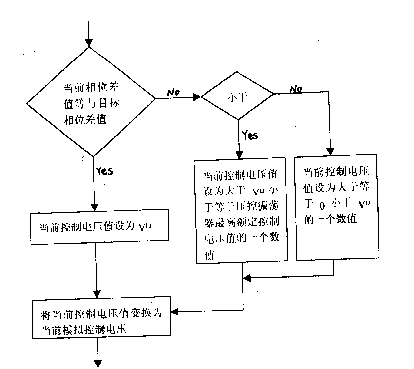
[0020] Refer to attached picture. The synchronous processing method of the clock output signal in the digital communication equipment of the present invention, it utilizes the digital phase-locked loop to adjust the clock output signal Sout to the same frequency as the clock input signal Sin, and the digital phase-locked loop is composed of phase detector 1, digital The loop filter controller 2, the digital-to-analog converter 3, and the voltage-controlled oscillator 4 are composed. After the target phase difference between the clock output signal and the clock input signal, such as 180 degrees, and the control voltage value V of the voltage-controlled oscillator after the clock output signal and the clock input signal have the same frequency D After being recorded in the memory of the digital loop filter controller in the digital phase-locked loop, the following cyclic steps are executed in sequence:

[0021] (1) The digital loop filter controller reads the current phase dif...


PUM


Abstract

The ivnention relates to a method for treating the synchronization of a clock output signal in a digit communication device. The method includes following procedures. (1) The output signal of clock is adjusted to the frequency that is the same frequency of the input signal of clock by use of a digit phase locked loop. (2) The value of target phase difference between the output signal of clock andthe input signal of clock is written to the memory of the filter controller in the digit loop circuit of the digitl phase lcoked loop. (3) After the output signal of clock and the input signal of clock have the same frequency, the value of control voltage Vd of the pressure-controlled oscillator in the digit phase locked loop is written to the memory of the filter controller in the digit loop circuit. (4) The output signal of clock is adjusted to the phase that is the same phase of the input signal of clock.

Description

technical field [0001] The invention relates to the field of signal processing in digital communications. Background technique [0002] At present, in digital communication equipment, a digital phase-locked loop is used to process the clock output signal and the clock output signal at the same frequency to make them have the same frequency. But in fact, due to factors such as the surrounding environment and internal stability, after each frequency locking is completed, the phase difference between the clock output signal and the clock input signal is always in a random state, which is not good for high-demand digital communications. Contents of the invention [0003] The technical problem to be solved by the present invention is to provide a simple and easy synchronous processing method of the clock output signal in digital communication equipment, so as to overcome the problem that the phase difference between the clock output s...

Claims


Application Information

Patent Timeline
Patent Type & Authority Applications(China)
IPC IPC(8): H04L7/02
Inventor 龚一航
Owner EASTERN COMM
Learn More