Conic-body for cathode-ray tube

A cathode ray and tube technology, applied in the direction of cathode ray tube/electron beam tube, cathode ray/electron beam tube shell/container, discharge tube, etc., can solve problems such as gap rise and time delay

Inactive Publication Date: 2002-10-23
NIPPON ELECTRIC GLASS CO LTD
View PDF0 Cites 1 Cited by
  • Summary
  • Abstract
  • Description
  • Claims
  • Application Information

AI Technical Summary

Problems solved by technology

At this time, on the minor axis and the major axis of the main body of the cone, since the distance from the central axis is different, the gap between the bottom mold and the press mold is increased, and the elongation time of the glass reaching the large opening is also different. The time delay for the glass on the major axis side to reach the large opening compared to

Method used


Image

  • Conic-body for cathode-ray tube
  • Conic-body for cathode-ray tube
  • Conic-body for cathode-ray tube

Examples


Embodiment Construction

[0018] Hereinafter, embodiments of the present invention will be described with reference to the drawings.

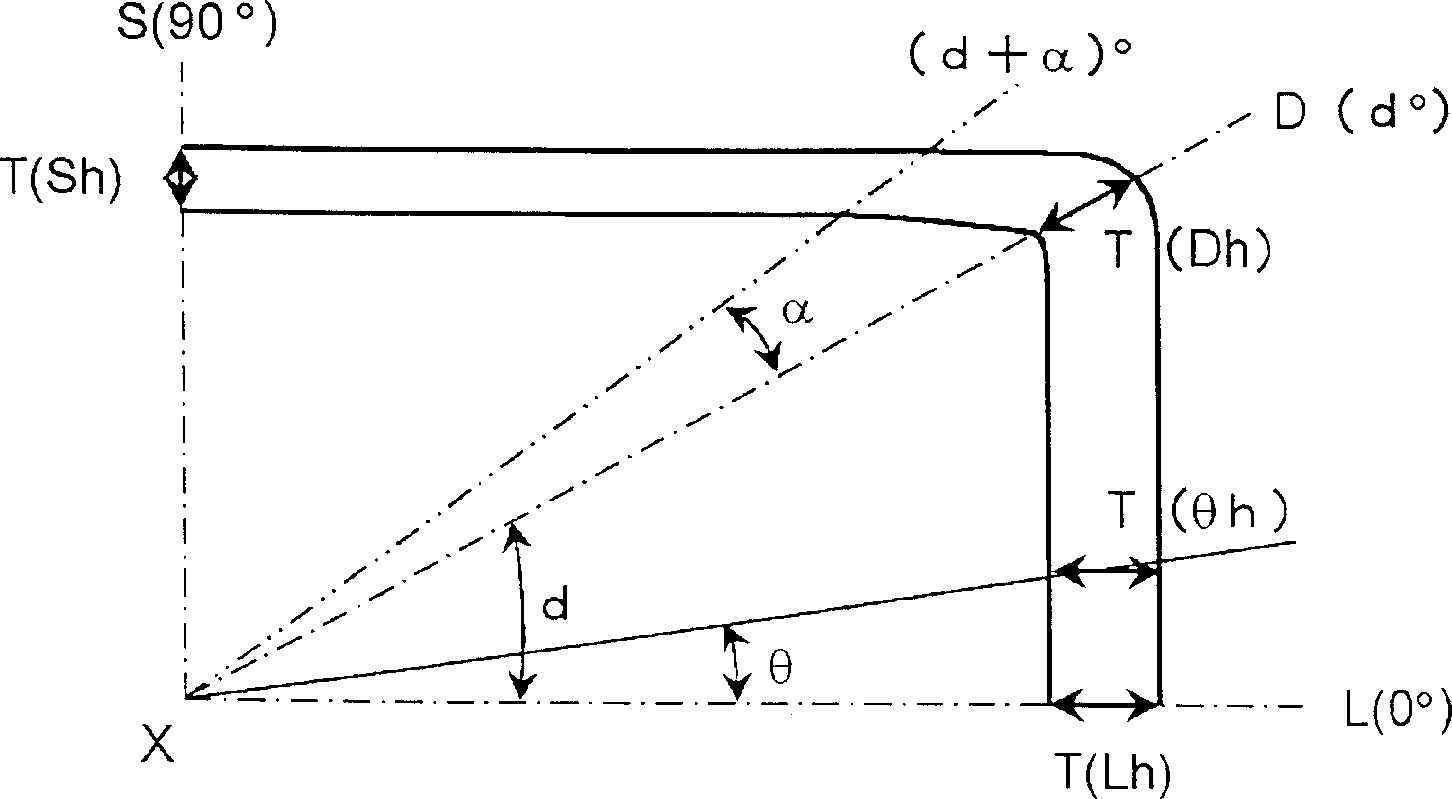
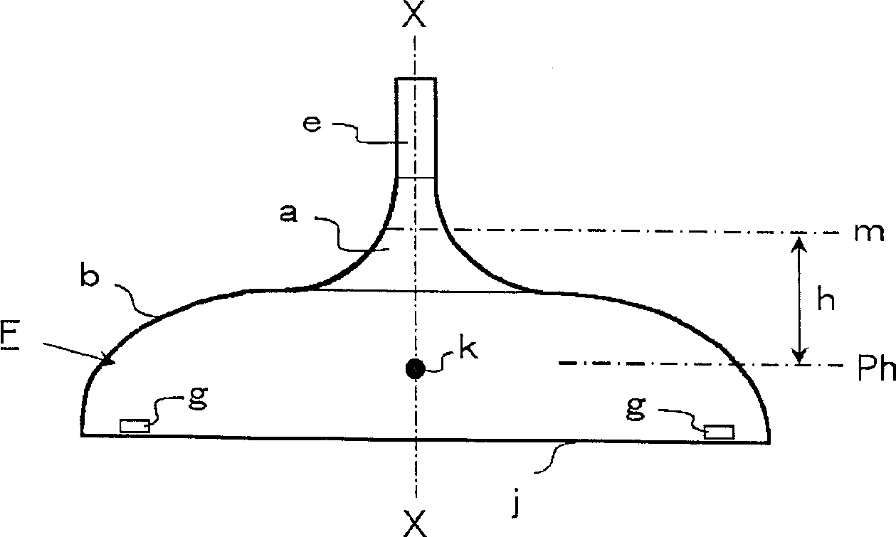
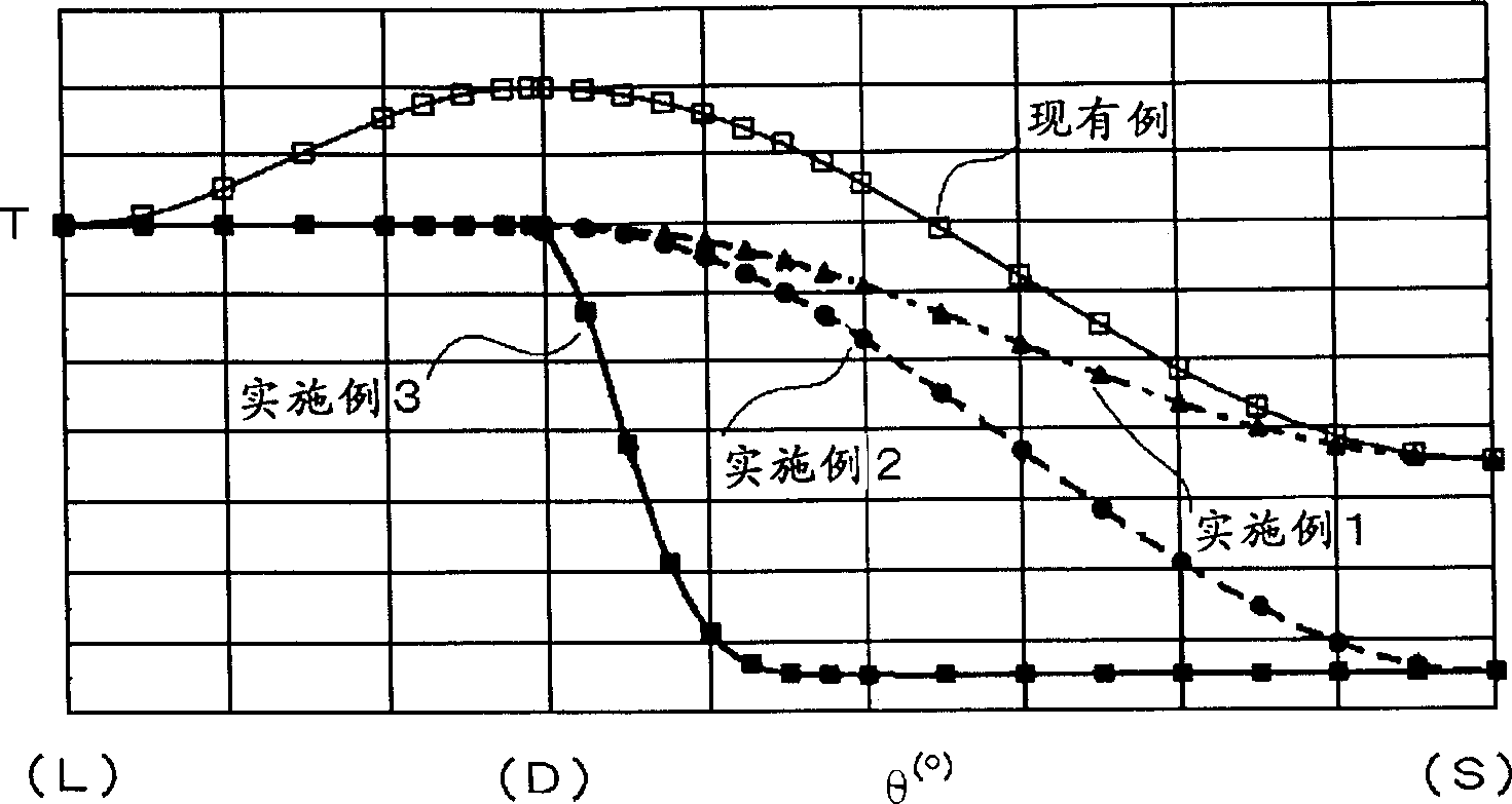
[0019] Fig. 1 (A) is the cross-sectional view of the 90 ° part (the first quadrant) of the cathode ray tube useful cone of the height h position from the reference line used to illustrate the wall thickness distribution of the present invention, and Fig. 1 (B) is the cone side view of the whole body, figure 2 It is a graph showing an example of the thickness distribution state of the 90° portion (first quadrant) of the cone of the present invention.

[0020] As shown in Figure 1(A) and Figure 1(B), the funnel F for a cathode ray tube is composed of a deflection yoke part a on the side of the small opening end and a body part b on the side of the large opening end, and the central axis X of the body part b is The vertical section is roughly quadrangular, with a major axis L, a minor axis S, and a diagonal axis D. Except for the neck portion e, the deflection yoke port...


PUM


Abstract

By setting the wall thickness on the long axis L as in the past, there is no loss of mechanical strength, and since the wall thickness in the area from the long axis L to the diagonal axis D is equal to the wall thickness on the long axis L and the diagonal axis D The difference in wall thickness between them is within 0.3mm, and they are formed approximately the same in the shape of the cone, and the wall thickness difference between the wall thicknesses on the minor axis S is within 0.3mm, which is approximately the same in the shape of the cone. The wall thickness region is formed within the range from 90°-(d+α)° to the minor axis S, so that the weight can be reduced.

Description

technical field [0001] The present invention relates to the weight reduction of the funnel of a cathode ray tube used for television reception. Background technique [0002] Generally, a cathode ray tube used for television reception includes a front panel portion, a rear funnel-shaped funnel portion, and a tube neck for accommodating an electron gun. And, as shown in Fig. 3 (A), (B), the cone part is made up of the deflection system part a on the end side of the small opening and the body part b on the end side of the large opening part, and is perpendicular to the central axis X of the body part b The cross-section of is roughly formed as a quadrangle, with a major axis L, a minor axis S, and a diagonal axis D. [0003] The wall thicknesses of the existing cone F' for cathode ray tubes at any height h on the major axis L, the minor axis S, and the diagonal axis D are T(Lh), T(Sh), and T(Dh) respectively , generally T(Sh)<T(Lh)<T(Dh), in the first quadrant of 0°≤θ≤9...

Claims


Application Information

Patent Timeline
Patent Type & Authority Applications(China)
IPC IPC(8): H01J29/02H01J29/86
CPCH01J29/861H01J2229/8606H01J29/02
Inventor 国武登志夫
Owner NIPPON ELECTRIC GLASS CO LTD
Why Eureka
Try Eureka