
Method for heating glass melting furnace with sectional combustion oxygen fuel burner mounted on the top

A glass melting furnace, oxy-fuel technology, which is applied to gas fuel burners, combustion with multiple fuels, and air/fuel supply for combustion, etc. , the effect of glass quality improvement

Inactive Publication Date: 2002-10-16
BOC GRP INC
View PDF5 Cites 20 Cited by
  • Summary
  • Abstract
  • Description
  • Claims
  • Application Information

AI Technical Summary

Problems solved by technology

However, the design does not take into account its role in the structure mounted on top

Method used


Image

  • Method for heating glass melting furnace with sectional combustion oxygen fuel burner mounted on the top
  • Method for heating glass melting furnace with sectional combustion oxygen fuel burner mounted on the top
  • Method for heating glass melting furnace with sectional combustion oxygen fuel burner mounted on the top

Examples


example 1

[0113] Example 1 retrofitted with top mounted oxy-fuel burners

[0114] A demonstration of the present invention is oxygen heating—transformed into 100% oxygen, and then converted into oxygen to increase heat, and finally form the traditional air fuel ignition of the existing 3-heat opening cross-fired reciprocating furnace. The furnace initially ignites all air fuel. The ignition of port #1 is replaced with at least one top mounted oxy-fuel burner. The furnace ignites the air-fuel that exchanges heat over the remaining two openings in the conventional manner. In the second stage, at least one top-mounted oxy-fuel burner is then used to replace the ignition of port #2 and conventionally ignite the air-fuel regenerating over the third port. In the third stage, the ignition of opening #3 is replaced with energy from the oxy-fuel burner already installed on the top. The furnace capacity was increased from 55 to 85 tons per day and the energy input was reduced from 23.5mm BTU / h...

example 2

[0115] Example 2 Burner and burner block with integral oxygen segments

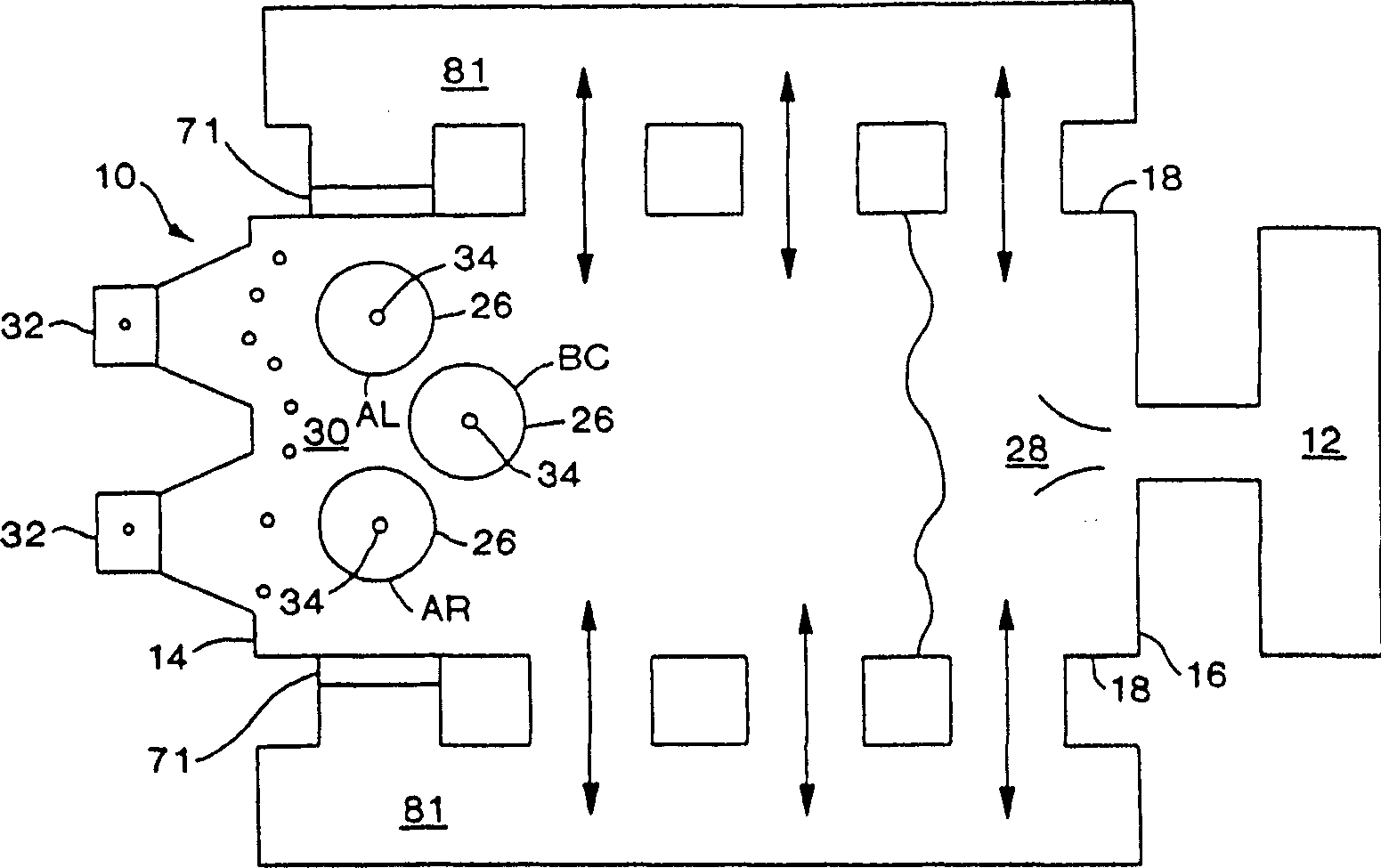
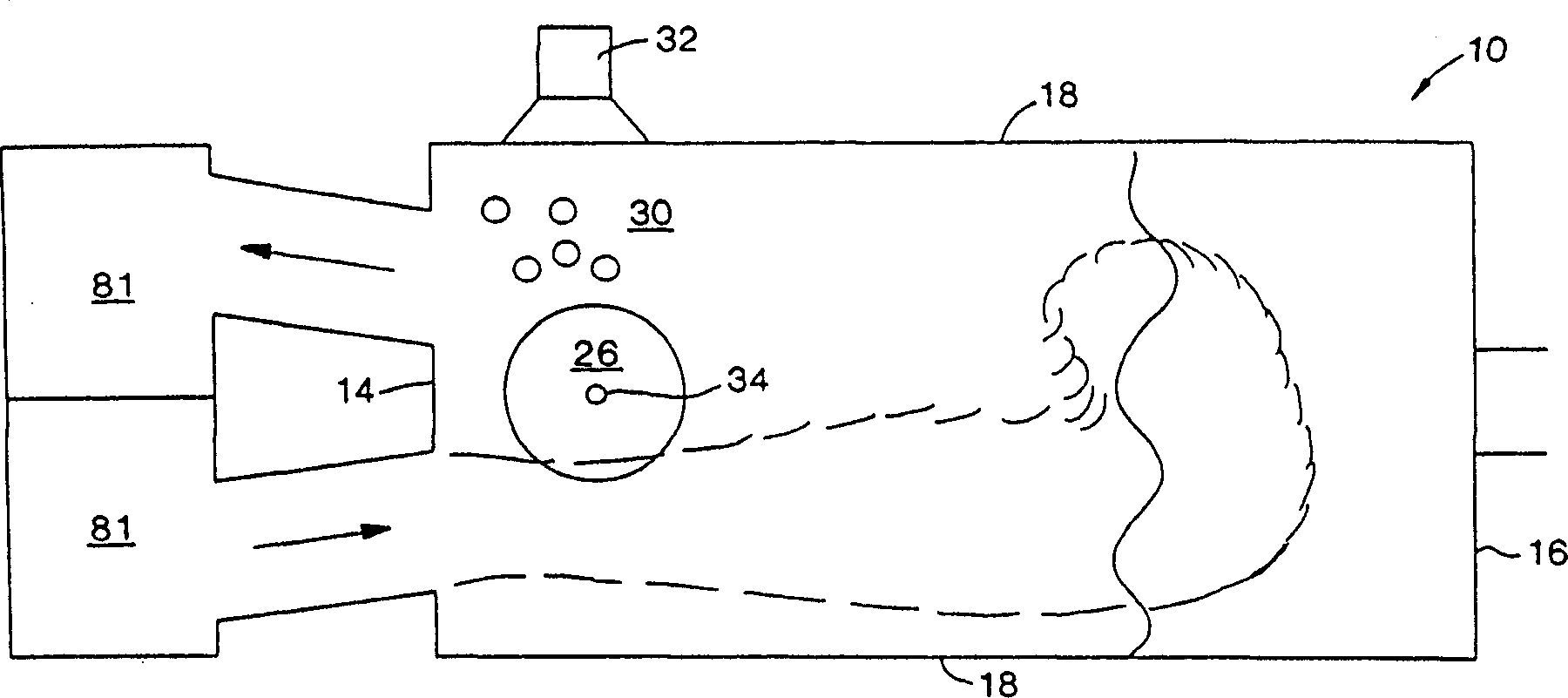
[0116] By means of the structure of the burner or the burner combined with the burner block shows an oxy-fuel burner provided with an oxygen integral section which increases heat transfer and reduces NO x . According to the invention, the roof 111 of the glass melting furnace 110 is provided with at least one integrally segmented burner 103 of this type. The burner 103 is ideally located above the raw batch 130, and is preferably angled so that the angle α( Figure 6 α) in the direction along the glass flow 104 in the furnace is approximately equal to 91° to 135°.

example 3

[0117] Example 3 Burner and burner block with external oxygen segments

[0118] See Figure 7 , the figure shows a burner 122 with a burner body 121 installed on the top of a glass melting furnace 111, the burner 122 has 2-8 oxygen injectors 112 outside the burner 122 and the furnace body 121, This burner can produce a higher heat transfer than an unstaged burner. The burner 122 is preferably angled from about 91° to about 135° relative to the glass surface and along the direction of glass flow in the furnace. According to this example, a stoichiometric ratio of 0% to about 90% of the injected oxygen is injected through the primary oxygen burner 133, and the remaining 100% to about 10% of the secondary combustion oxygen 134 is injected through the oxygen burner 112, which 112 makes an angle from about 0° to about 90° relative to the glass surface. As understood by those skilled in the art, the number, angle and degree of segmented openings are designed specifically for each...


PUM

PropertyMeasurementUnit
sizeaaaaaaaaaa

Abstract

An industrial glass furnace optionally housing a recuperator, regenerator, electrical heating, or other means for providing heat to the glass batch, having at least one staged combustion oxy-fuel burner in the top of the furnace providing heat to melt the glass batch by providing a flow of fuel to the oxy-fuel burner; providing a flow of gaseous oxidizer associated with the oxy-fuel burner; injecting the fuel and oxidizer into the furnace; and burning the fuel to cause At least a portion of the combustion is achieved in the vicinity of the glass-forming material such that convective and radiative heat transfer to the glass-forming material is enhanced without significantly disturbing the glass-forming material. In one embodiment, the oxy-fuel burner is adapted to inject liquid fuel. In another embodiment, the oxy-fuel burner is adapted for staged combustion of fuel and includes at least one external oxidizer injector and two internal fuel injectors, the innermost fuel injector being adapted for high velocity fuel injection, and the innermost fuel injector Another fuel injector between the injector and the external oxidizer injector is suitable for low speed fuel injection.

Description

[0001] Cross reference to related applications [0002] This application is a continuation-in-part of US Application No. 09 / 374,921 filed August 16,1999. technical field [0003] The present invention relates to the use of top mounted oxy-fuel burners for glass melting. The invention also relates to the use of at least one oxy-fuel burner in the top of the glass melting furnace with internal or external combustion sections. The invention is applicable to both furnaces burning 100% oxy-fuel, as well as furnaces heated by electric or non-oxy-fuel means, such as one or more air-fuel furnaces or combinations thereof. Background technique [0004] In one embodiment, the present invention involves the use of at least one oxy-fuel burner in the top of a glass melting furnace to expand or maintain existing capacity while reducing electrical heat gain or damage to existing Results of heat recovery equipment such as recuperators or recuperators. The process involves replacing a por...

Claims


Application Information

Patent Timeline
Patent Type & Authority Applications(China)
IPC IPC(8): F23C5/08C03B5/00C03B5/16C03B5/235F23C5/00F23C6/04F23C99/00F23D14/02F23D14/22F23D14/32F23D17/00F23L7/00F27D7/02
CPCC03B5/193C03B5/2353C03B2211/30C03B2211/40C03B2211/60F23C5/00F23C6/047F23D14/02F23D14/32F23D17/002F23L7/00F23L2900/07005Y02P40/57Y02E20/34Y02P40/50C03B5/00
Inventor N·G·辛普森G·F·普鲁沙T·G·克莱顿A·P·理查德森J·R·李布兰科
Owner BOC GRP INC
Learn More