
Receiver with automatic gain control

A technology of automatic gain control and signal receiving device, which is applied in the direction of gain control, amplification control, transmission control/equalization, etc., and can solve problems such as technical impossibility

Inactive Publication Date: 2002-09-25
THOMSON LICENSING SA
View PDF0 Cites 3 Cited by
  • Summary
  • Abstract
  • Description
  • Claims
  • Application Information

AI Technical Summary

Problems solved by technology

In the case of high ADC sampling frequencies, these considerations may lead to technically constituted impossibility

Method used


Image

  • Receiver with automatic gain control
  • Receiver with automatic gain control
  • Receiver with automatic gain control

Examples


Embodiment Construction

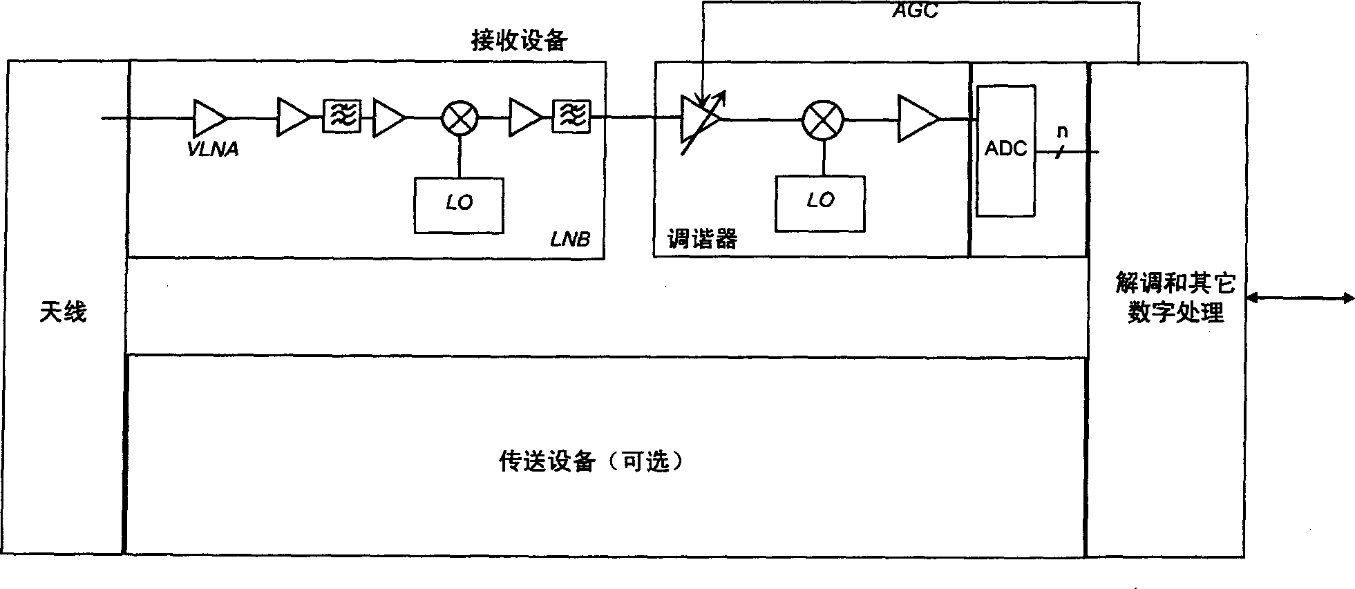
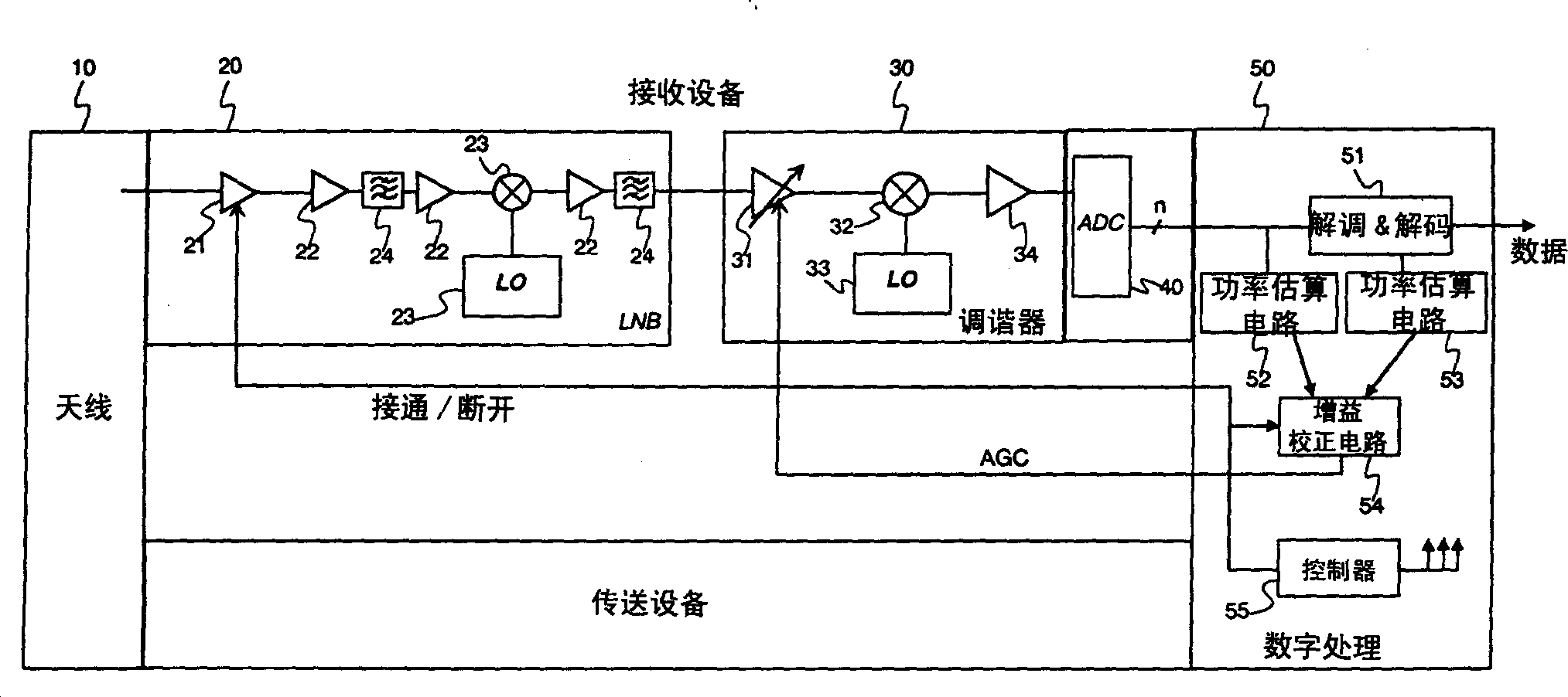
[0015] figure 2 A preferred embodiment of a spaceborne data transmission / reception device is depicted. figure 2 Draw a more specific detailed block diagram of the receiving device. The delivery equipment is not described in detail because any type of delivery equipment could be used.

[0016] The antenna 10 is connected to a low noise block 20, known by the acronym LNB. The antenna 10 is composed of wave focusing means, such as mirrors or lenses, and converting means for electric signal waves. The received waves typically have a frequency such as above 10 GHz. If the transmission / reception device works in a duplex mode, a duplexer can be added between the antenna 10 and the LNB 20 .

[0017] The LNB 20 comprises at least one first low-noise amplifier stage 21, for example of the VLNA type, one or more other low-noise amplifiers 22, means for converting the received signal into an intermediate frequency band (for example between 500 MHz and 2 GHz) 23, and one or more fil...


PUM


Abstract

The invention aims to minimize the analogue / digital converter over-dimensioning within the framework of reception of signals originating from a satellite and exhibiting power levels which can vary over time. The invention proposes a technique of automatic gain control which handles the setting of the noise level associated with the amplified signal. The automatic gain control is achieved by neutralizing the signal received by the antenna, and by adjusting the gain during the neutralization of the signal received until a predetermined noise level is obtained at the end of the reception facility. The invention also pertains to a device comprising the means for implementing the method. <IMAGE>

Description

technical field [0001] The invention relates to a device with automatic gain control. Such devices are used in equipment for receiving radio frequency communications, especially satellite type communications equipment. Background technique [0002] In conventional satellite-based communication systems, the receive input stage is built around a low noise amplifier, such as a VLNA (stands for Very Low Noise Amplifier) ​​type amplifier. The structure of a conventional receiver of a transmitting / receiving device combined with an antenna is given below. In the receive path, a first stage called a VLNA stage amplifies the useful signal output by the antenna while minimizing the effect of noise. When receiving, one of the main problems to be solved is the automatic gain control (hereinafter referred to as AGC) that enables it to precisely adjust the gain of the receiving device so that the signal amplitude input to the analog-to-digital converter (hereinafter referred to as ADC) ...

Claims


Application Information

Patent Timeline
IPC IPC(8): H03G3/30H03G3/20H03M1/08H03M1/18H04B1/16H04B7/005H04N5/52H04N7/20
CPCH03M1/08H03M1/185H04N5/52H04N7/20H04B7/005
Inventor 让-伊夫·勒纳乌尔帕特里斯·伊尔茨兰奥利维耶·莫卡尔
Owner THOMSON LICENSING SA
Learn More