Thin electric connector with locking function

A technology of electrical connectors and connectors, which is applied in the direction of connecting, joining/disconnecting connected parts, two-part connecting devices, etc., which can solve the problems of large displacement, difficulty in reducing the thickness of the connector, and large operating force

Inactive Publication Date: 2002-07-24
JAPAN AVIATION ELECTRONICS IND LTD
View PDF1 Cites 5 Cited by
  • Summary
  • Abstract
  • Description
  • Claims
  • Application Information

AI Technical Summary

Problems solved by technology

However, in order to manipulate its working part, this kind of locking structure requires a large displacement and a large manipulation force
Therefore, the use of the lock structure makes it difficult to reduce the thickness of the connector
Therefore, it is inappropriate or unfavorable to use a locking mechanism in a connector for connecting a liquid crystal display

Method used


Image

  • Thin electric connector with locking function
  • Thin electric connector with locking function
  • Thin electric connector with locking function

Examples


Embodiment Construction

[0017] Specific embodiments of the present invention will be described below with reference to the accompanying drawings.

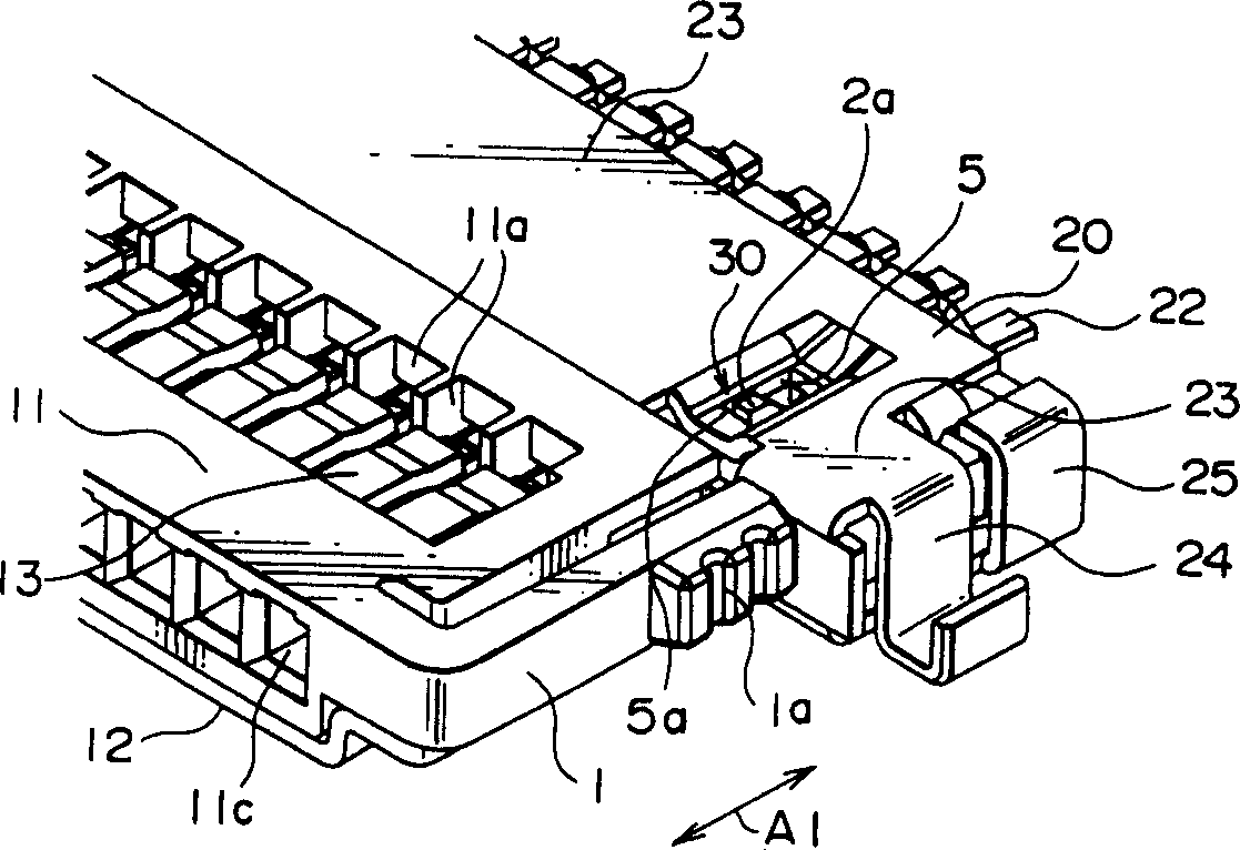
[0018] refer to figure 1 and 2 , an electrical connector comprising: a first or plug connector 10, a second or receptacle connector 20, the two cooperate with each other along a first direction A1; a pair of locking mechanisms 30, each of which is through the plug formed in combination with socket connectors 10 and 20 in a manner that will be clearly described hereinafter.

[0019] Also refer to Figure 3-6 , the plug connector 10 includes a box-shaped insulator 11 whose dimension along the thickness direction as the second direction A2 is small. The insulator 11 has a plurality of contact receiving portions 11a, a contact portion 11b fitted on the receptacle connector 20, and a plurality of insertion holes 11c for receiving lead wire ends and the like. The lower surface of the insulator 11 is covered by a metal shell 12 . A plurality of plug contact...


PUM


Abstract

An electrical connector includes first and second connectors fitted to each other in a first direction. The first connector includes a locking member extending in the first direction and displaceable in a second direction, a lever extending from the locking member in a third direction, a protruding portion protruding from the lever in the second direction, and an unlocking arm extending in the first direction and displaceable in the third direction. The second connector has a locking portion to be engaged with an engaging portion of the locking member in the first direction when the first and the second connectors are fitted to each other. Engagement between the engaging portion and the locking portion is released when the protruding portion is pressed by a cam portion of the unlocking arm to displace the locking member in the second direction through the lever.

Description

technical field [0001] The invention relates to a thin electrical connector with locking function, which is used to maintain the connection state. Background technique [0002] Thin electronic devices such as notebook personal computers may have liquid crystal displays. To connect an LCD display, various types of connectors are used. With the need to further reduce the thickness of electronic devices, the thickness of liquid crystal displays used therein is also reduced. This requires that the thickness of the connector used to connect the liquid crystal display is also reduced. But in a connector whose thickness is reduced, the connection strength may not be large enough. In order to increase or enhance the connection strength, insulating tape is commonly used, or bonded with an adhesive, so that the connector in the connected state is fixed. [0003] On the other hand, a locking structure for maintaining a common connector in a connected state is disclosed in, for exam...

Claims


Application Information

Patent Timeline
Patent Type & Authority Applications(China)
IPC IPC(8): H01R13/633H01R13/62H01R13/627
CPCH01R12/7041H01R23/7036H01R12/7005H01R23/7005H01R13/6273H01R13/62
Inventor 镰田一史带金宏明
Owner JAPAN AVIATION ELECTRONICS IND LTD
Why Eureka
Try Eureka