
Device and method for determining hydraulic unit output speed in hydraulic mechanical gearing means

A hydraulic unit and transmission technology, applied in transmission, transmission control, fluid transmission, etc., can solve the problem of expensive directional Hall effect sensor and magnetic ring, low output speed correction rate of hydraulic unit, low speed pulse frequency, etc. question

Inactive Publication Date: 2002-04-24
DEERE & CO +1
View PDF0 Cites 7 Cited by
  • Summary
  • Abstract
  • Description
  • Claims
  • Application Information

AI Technical Summary

Problems solved by technology

One drawback of this approach is that the directional hall effect sensor and magnetic ring are relatively expensive
Another defect is that when the hydraulic unit is close to the zero stroke, the frequency of the speed pulse is also low due to the low output speed of the hydraulic unit
Therefore, the correction rate for measuring the output speed of the hydraulic unit is also low

Method used


Image

  • Device and method for determining hydraulic unit output speed in hydraulic mechanical gearing means
  • Device and method for determining hydraulic unit output speed in hydraulic mechanical gearing means
  • Device and method for determining hydraulic unit output speed in hydraulic mechanical gearing means

Examples


Embodiment Construction

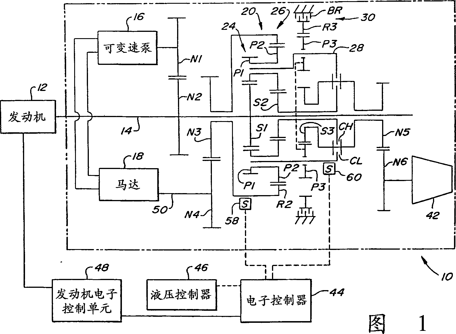
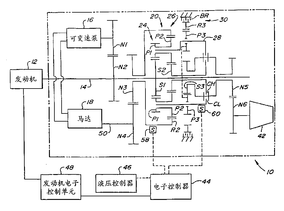
[0008] The hydromechanical transmission according to the invention is shown in FIG. 1 and indicated by reference 10 . The transmission 10 is adapted to be driven by an engine 12 having an output shaft 14 . The transmission further comprises a hydraulic unit comprising a variable speed pump 16 and a motor 18 driven by the pump 16 . The output shaft 14 of the engine drives a hydraulic pump 16 through gears N2 and N1.

[0009] The transmission includes a planetary gear system 20 having first and second planetary gear sets 24 and 26 . The planetary gear sets have a common planetary gear carrier 28 on which are mounted integral planetary gears P1 and P2 respectively of the two planetary gear sets. A separate ring gear R2 is used to mesh with the planetary gears P2. The engine output shaft 14 also drives the sun gear S1 of the first planetary gear set 24 at the same time. The second planetary gear set 26 has a sun gear S2.

[0010] The transmission has two clutches, a low range...


PUM


Abstract

The output speed of a hydrostatic unit in a transmission is determined using a pair of variable reluctance sensors, one on a gear driven by the hydrostatic unit output and the other on the carrier of the planetary system. One of the two sensors will always be measuring a relatively high speed from which the hydro output is directly determined or indirectly determined using the current engine speed. Thus the frequency of the speed sensor used to determine the hydrostatic unit output speed is not decreased at slow hydrostatic unit output speeds.

Description

technical field [0001] The present invention relates to a hydromechanical transmission with a hydraulic unit, in particular to a device and method for determining the actual output speed of the hydraulic unit. Background technique [0002] The controller of the hydromechanical transmission device determines a given output speed for the hydraulic unit according to the change of the input index. For proper control, there needs to be a feedback of the achieved output speed of the hydraulic unit to the controller. Previously, such feedback has been achieved with a directional Hall effect sensor and a magnetic ring mounted on the output shaft of the hydraulic unit or on a gear driven by the output shaft of the hydraulic unit. A drawback of this approach is that the directional Hall effect sensor and magnetic ring are relatively expensive. Another disadvantage is that when the hydraulic unit is close to zero stroke, the frequency of speed pulses is low due to the low output spee...

Claims


Application Information

Patent Timeline
IPC IPC(8): F16H47/04F16H59/38F16H59/40F16H59/42F16H59/46F16H61/02
CPCF16H59/42F16H59/46F16H59/38F16H59/40F16H47/04F16H2037/088
Inventor T·L·古德奈特D·R·约翰森D·D·迪尔克斯W·格尔纳
Owner DEERE & CO
Learn More