
Method of controlling single spindle driving motor of spinning machine

A technology for driving motors and spinning machines, which can be used in spinning machines, continuously wound spinning machines, electronic commutators, etc., and can solve problems such as complex structure and increased cost.

Inactive Publication Date: 2002-04-10
TOYOTA IND CORP
View PDF0 Cites 2 Cited by
  • Summary
  • Abstract
  • Description
  • Claims
  • Application Information

AI Technical Summary

Problems solved by technology

Therefore, the structure becomes complicated and the cost increases

Method used

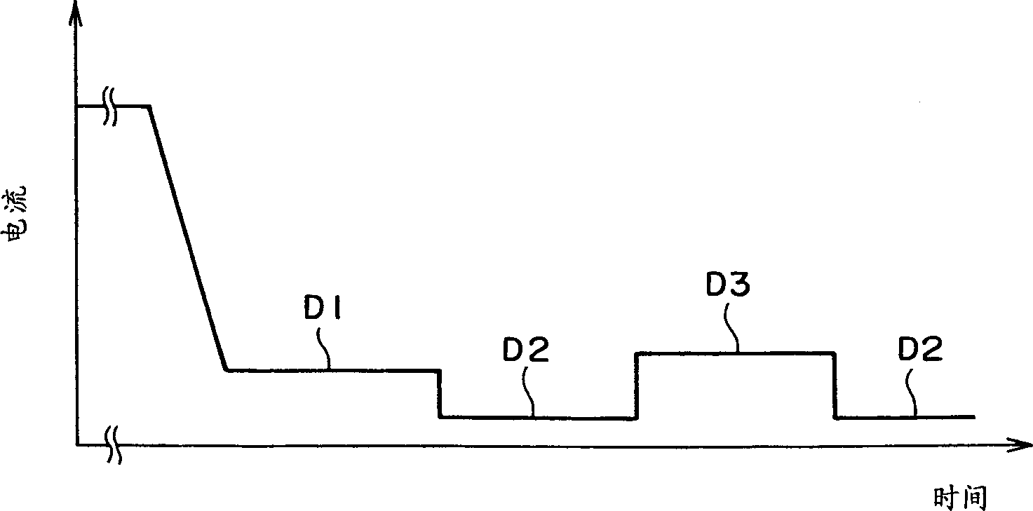
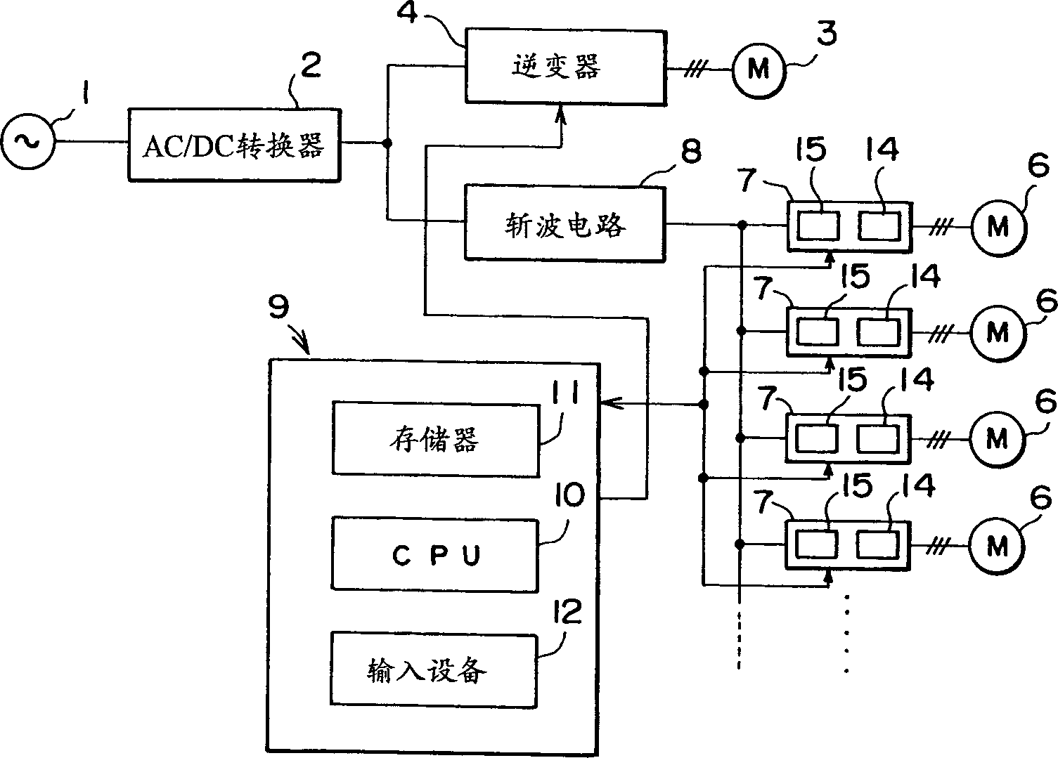
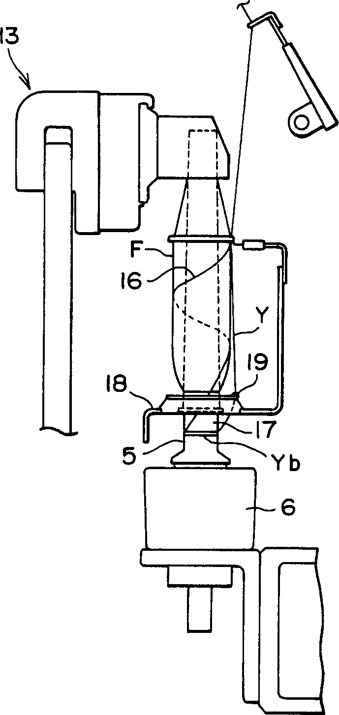

Image

  • Method of controlling single spindle driving motor of spinning machine
  • Method of controlling single spindle driving motor of spinning machine
  • Method of controlling single spindle driving motor of spinning machine

Examples


Embodiment Construction

[0017] The following will refer to Figure 1-3 An embodiment of a single-spindle-driven ring spinning machine according to the invention is described.

[0018] Such as figure 2 As shown, an AC power source 1 is connected with an AC / DC converter 2 . A traction motor 3 constituting a traction section drive system is connected to an AC / DC converter 2 through an inverter 4 . The traction section drive system is connected to a hoist drive system (not shown) for synchronous operation. The hoist drive system is used to raise or lower a ring plate and a hook plate angle through a rotary transmission device (not shown), and the traction Motor 3 also drives the lift drive system.

[0019] The respective spindles of the spinning machine are equipped with single spindle drive motors 6 for individually driving each spindle 5 ( image 3 shown). A synchronous motor is used for the single spindle drive motor 6 . In this embodiment, a switched reluctance motor (SR motor) is used. The s...


PUM


Abstract

In a spinning machine for independently driving each spindle (5) by an individual motor (6), a synchronization motor is used as the motor and is controlled through an inverter (14). At least when a bobbin is pulled out after a doffing stop, each of the motors is supplied with a direct current (D3), and a holding force for holding the spindle in a stop state is increased.

Description

technical field [0001] The present invention relates to a method of controlling a single spindle drive motor of a spinning machine, such as a ring spinning machine or a ring twisting machine, which uses a single motor to independently drive the respective spindles. Background technique [0002] More recently a machine has been proposed with multiple spindle drive motors so that each spindle has its own motor instead of only one motor driving all the spindles on the spinning frame. This has been proposed for the purpose of making it possible to arrange a large number of spindles on the spinning frame or to increase the rotational speed of the spindles. In the case of providing a single spindle drive motor in each spindle as described above, a spindle rotation problem may occur at the time of doffing, which is different from the case of the ring spinning machine belt drive method in which one belt drives a plurality of spindles. [0003] The reason for this is that when a thr...

Claims


Application Information

Patent Timeline
Patent Type & Authority Applications(China)
IPC IPC(8): D01H1/244D01H7/22D01H9/14
CPCD01H1/244D01H9/14
Inventor 蓑岛纪元筱崎丰金子政司
Owner TOYOTA IND CORP
Learn More