
Connector for card

A technology of plug-in device and contact part, which is applied in the direction of two-part connection device, coupling device, device for preventing wrong connection, etc., can solve the problem of changing contact pressure, etc., and achieve the effect of overall miniaturization

Inactive Publication Date: 2002-01-23
ALPS ALPINE CO LTD
View PDF0 Cites 2 Cited by
  • Summary
  • Abstract
  • Description
  • Claims
  • Application Information

AI Technical Summary

Problems solved by technology

In this method, since the length from the supporting position of each connection terminal to the contact portion is different, there is a problem of changing the contact pressure with the contact portion of the IC card corresponding to this length.

Method used


Image

  • Connector for card
  • Connector for card
  • Connector for card

Examples


Embodiment Construction

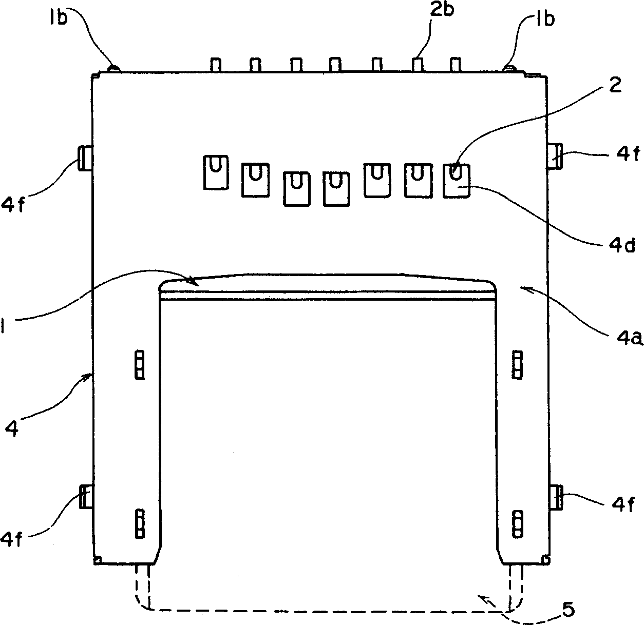
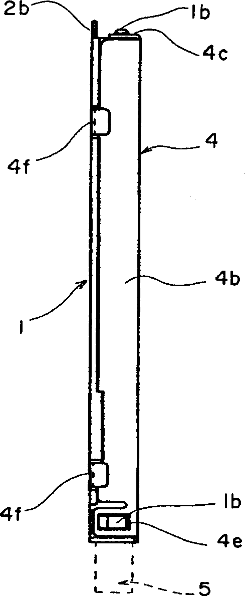
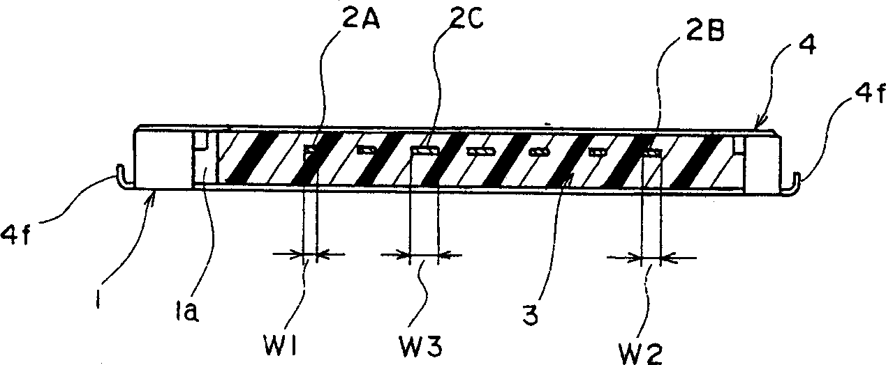
[0026] In the drawing, the frame 1 is made of insulating material such as synthetic resin and has a box shape with its upper surface and front open. In the center of the chassis 1 is formed an accommodating portion 1 a for inserting an IC card 5 which will be described later. A head portion 3 in which a plurality of connection terminals 2 made of conductive metal plates are arranged in parallel is provided on the front end. The head 3 is integrally made with the frame 1, but they can also be combined and assembled into one body after separate molding.

[0027] On the front end portion of the frame 1 and its side end portions, coupling protrusions 1b for coupling to a cover portion 4 described later are formed.

[0028] The connecting terminal 2 is supported such that the supporting portion 2a is integrated with the head portion 3 by inserting or the like. On one end of the connecting terminal 2, a soldering portion 2b protruding from the head portion 3 to the outside of the ...


PUM


Abstract

According to the present invention, a connector device for card in which supporting positions of the respective connection terminals with respect to the header are formed on the same straight line without being shifted forward and backward and rigidity of the respective supporting portions get greater as the length to the contact portion gets greater, so that the contact pressures of the respective connection terminals are uniform and the miniaturization of the whole connector device can be accomplished, is provided. The connector device for card comprises a header 3 provided side by side with a plurality of connection terminals 2 made of conductive metal plate; and a frame 1 which the header 3 is arranged at one end thereof and which a card 5 with a plurality of contacts 5a capable of being connected to the connection terminals 2 is fitted, wherein the connection terminals 2 are provided with a supporting portion 2a supported to the header 3 and a contact portion 2c elastically contacted with the contact 5a of the card at a free end extended from the supporting portion 2a, respectively, and wherein the connection terminals 2 are so formed that the supporting portions 2a are provided side by side on the same straight line having a direction perpendicular to a card-inserting direction, that lengths from the supporting portions 2a to the contact portions 2c are formed differently and at the same time, and that as the length from the supporting portion 2a to the contact portion 2c gets longer, rigidity of the supporting portion 2a get greater.

Description

technical field [0001] The present invention relates to the structure of an integrated circuit (IC) card used for storage media such as personal computers, etc., and a card insertion device for MMC cards (multimedia cards) used in electrical appliances such as digital cameras. Background technique [0002] As an extension recording device for a personal computer or the like, a socket device for an integrated circuit card is generally used. As the storage carrier of the plug-in device for the integrated circuit card, people gradually and widely use the integrated circuit card. [0003] Insert the integrated circuit card into the socket device for the integrated circuit card to write and read the necessary information, and a plurality of contact parts are set on the integrated circuit card, and on the socket device side for the integrated circuit card, corresponding to these The contact part is arranged at the position and is provided with the head part of the connection term...

Claims


Application Information

Patent Timeline
Patent Type & Authority Applications(China)
IPC IPC(8): B42D15/10G06K7/00G06K7/01G06K13/08G06K17/00H01R13/64H01R24/00H01R107/00
CPCH01R23/7068Y10S439/91H01R12/721
Inventor 小口亘
Owner ALPS ALPINE CO LTD
Learn More