
Coupler for connecting wire

A plug and wire technology, applied in the field of wire connection plugs, can solve the problems of unstable contact pressure of wires 5 and 7, inability to obtain circuit connection characteristics, and change in contact resistance.

Inactive Publication Date: 2007-07-18
SMK CO LTD
View PDF3 Cites 0 Cited by
  • Summary
  • Abstract
  • Description
  • Claims
  • Application Information

AI Technical Summary

Problems solved by technology

[0016] On the other hand, in the structure of the electric wire connection plug 200 that obtains the holding force of the lead wires 5, 7 only by clamping the lead wires 5, 7 as described above, there is a limit in ensuring the holding force, and it cannot be completely to solve the problem
[0017] Again, since the sharp-angled front end of the plate spring 223 is crimped and engaged with the stripped portion 250 of the lead 5,7, the peeled portion 250 is easily partially broken, and the lead 5,7 cannot be reused repeatedly due to the breakage.
[0018] Some of the partially broken wires at the stripped part 250 may remain in the box body 210 or in the machine-side socket 127, which may result in poor insulation.
[0019] Furthermore, the positions of the front ends of the leaf springs 223 abutting against the wires 5, 7 are different each time because of the insertion state of the wires 5, 7, so the amount of deflection of the leaf springs 223 will change, resulting in a discrepancy with the wires 5 and 7. , 7 The instability of the contact pressure
Therefore, the contact resistance will change, and the circuit connection characteristics cannot be obtained as the original design value

Method used


Image

  • Coupler for connecting wire
  • Coupler for connecting wire
  • Coupler for connecting wire

Examples


Embodiment Construction

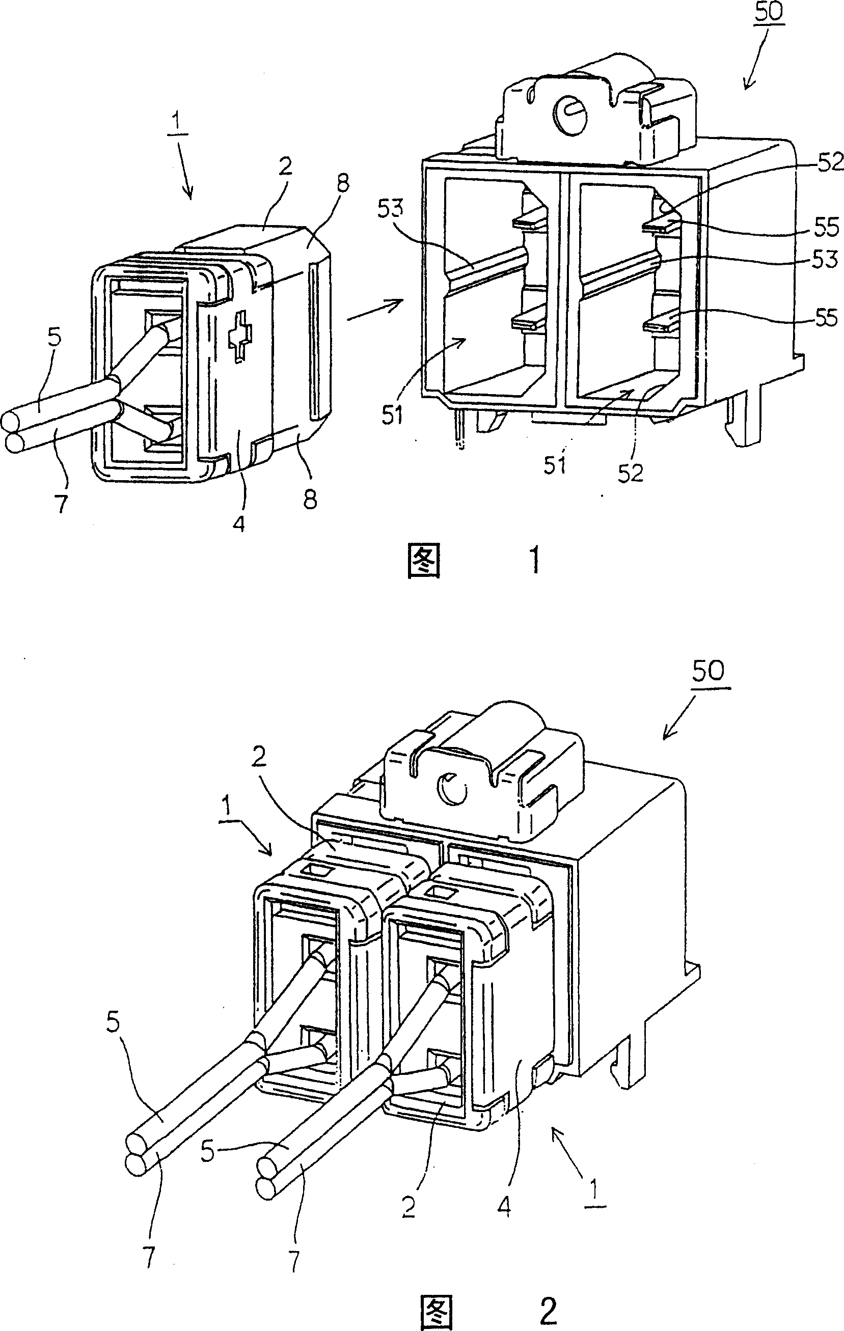
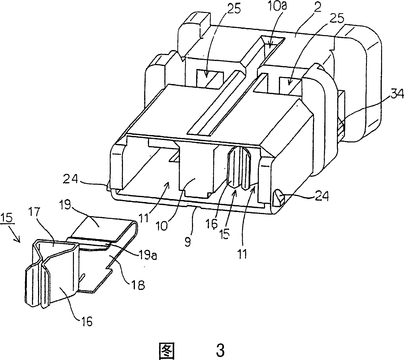
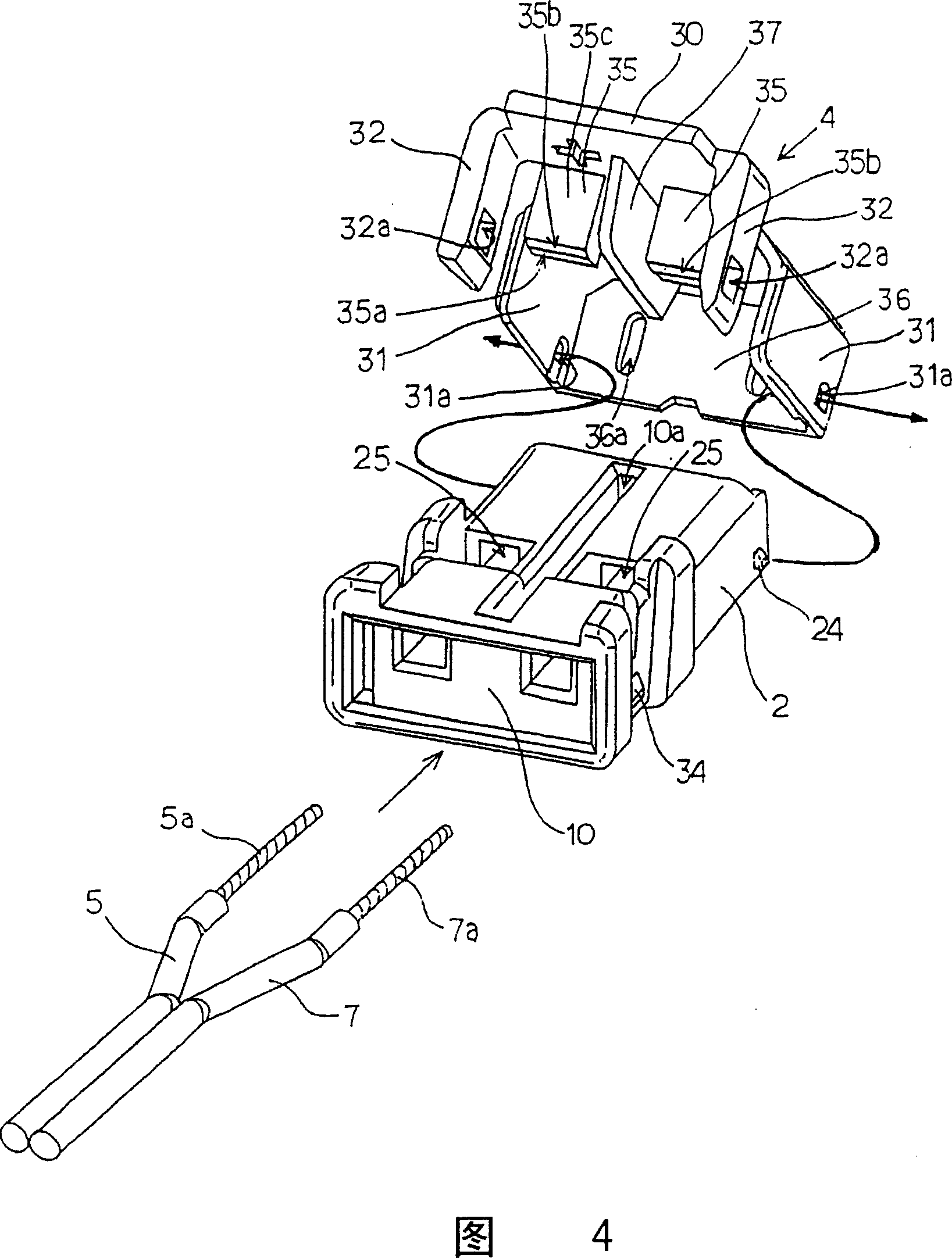
[0052] Hereinafter, an electric wire connection plug (hereinafter referred to as a plug) 1 according to an embodiment of the present invention will be described with reference to FIGS. 1 to 6 . The plug 1 is formed of a box body 2 and a cover body 4 rotatably mounted on the box body 2 to form its external shape.

[0053] The plug 1 is used, for example, to connect an amplifier and a speaker of an audio device, and is detachably inserted into a rectangular parallelepiped connection recess 51 of a socket 50 on the device side. Therefore, in a state where the cover body 4 is turned to cover the case body 2 , it has a vertically long rectangular cross-sectional shape corresponding to the connection recess 51 .

[0054] In this embodiment, the two connection recesses 51, 51 are recessed side by side to provide a structure for two-channel connection on the socket 50. As shown in FIG. 2, the connection recesses 51, 51 are used for Insert the corresponding plug 1, 1. In FIG. 1 , 55 ...


PUM


Abstract

The present invention relates to a plug for the connection of wires, which provides sufficient retaining force for lead-in wires (5, 7) to prevent the lead-in wires (5, 7) from breaking, and provides contact resistance of predetermined value.

Description

technical field [0001] The present invention relates to a plug for connecting wires to audio equipment, etc., and more particularly, the present invention relates to a plug for connecting wires composed of a pair of L and R signal lines to speakers, audio equipment, etc. plug. Background technique [0002] As a device that uses wires to distribute lines, such as amplifiers and speakers of audio equipment, they are connected by wires consisting of a pair of L and R signal wires. To connect the lead wires to these devices, the end sheath of the lead wires is usually stripped off, and as shown in FIG. [0003] The lever terminal 103 resists the torque of the coil spring 107 to rotate the lever 105 clockwise in the drawing, and inserts the end of the stripped wire 109 into the insertion hole 111 . Then, if the handle 105 is returned to the original position, the wire 109 will be bitten between the contact fitting 113 integrally arranged on the lever 105 and the contact fitting...

Claims


Application Information

Patent Timeline
Patent Type & Authority Patents(China)
IPC IPC(8): H01R24/00H01R13/58H01R4/48H01R4/50H01R13/46H01R13/64
CPCH01R24/68H01R4/5008H01R13/64H01R2103/00H01R23/10H01R4/48
Inventor 松田健小室雅司
Owner SMK CO LTD
Learn More