


Quick Research
Generate reliable direction feasibility study reports for your R&D in just a few steps.

Technical Q&A
Discover and master advanced knowledge NOW. Basics, ideas, possibilities, all at once.

Find Solutions
As an expert in R&D theories, this can generate solutions to your technical problems instantly.

Evaluate Feasibility
Analyze your overall solution with one click, know your potential R&D risks in advance.

Monitor Landscape
Get weekly tech updates, stay abreast of the latest tech innovations and key insights.
Rolling mill
A rolling mill and roll technology, applied in the direction of metal rolling stands, metal rolling, metal rolling, etc., can solve the problem of inability to prevent rolling vibration.
- Summary
- Abstract
- Description
- Claims
- Application Information
AI Technical Summary
Problems solved by technology
Method used
Image


Examples
no. 1 example
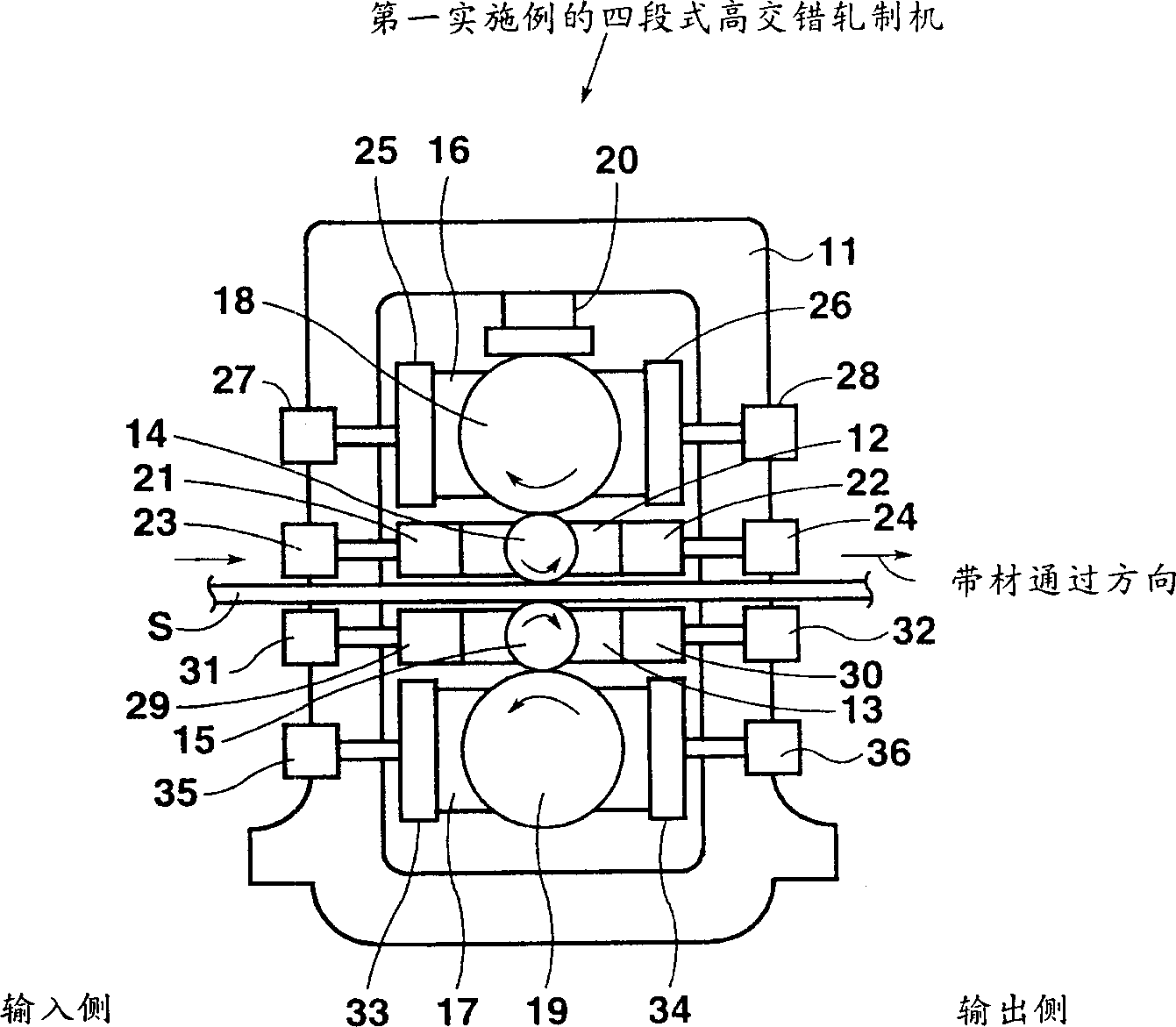
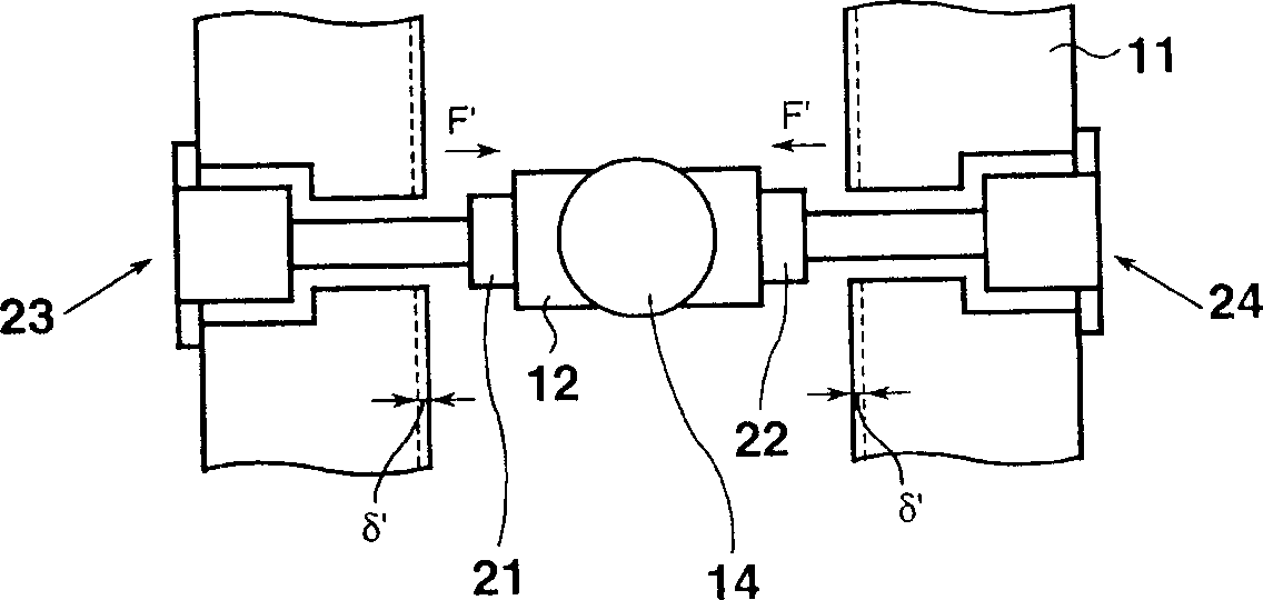
[0045] Such as figure 1 As shown, in the four-stage high stagger rolling mill as the rolling mill according to the first embodiment, a pair of upper and lower work roll chocks 12 and 13 are supported within a casing 11 . Shaft portions of a pair of upper and lower work rolls 14 and 15 are rotatably supported by upper and lower work roll chocks 12 and 13, respectively, and the upper and lower work rolls 14 and 15 face each other. A pair of upper and lower backup roll chocks 16 and 17 are supported above and below the upper and lower work roll chocks 12 and 13 . The shaft portions of a pair of upper and lower backup rolls 18 and 19 are rotatably supported by upper and lower backup roll chocks 16 and 17, respectively. The upper backup roll 18 and the upper work roll 14 face each other, and the lower backup roll 19 and the lower work roll 15 face each other. The unscrewing device 20 is provided in the upper part of the housing 11, and the device 20 is used to apply a rolling lo...
no. 2 example
[0057] Such as Figure 8 As shown, in the staggered rolling mill according to the second embodiment, upper and lower work rolls 64 and 65 are rotatably supported by a pair of upper and lower work roll chocks 62 and 63 supported by a casing 61 . Upper and lower backup rolls 68 and 69 are rotatably supported by a pair of upper and lower backup roll chocks 66 and 67 which are supported by housing 61 . A unscrewing device 70 for applying a rolling load is provided in an upper portion of the casing 61 . Upper crossheads 71 and 72 for supporting the upper chocks 62 and 66 are provided on the input side and the output side of the housing 61 . The upper crossheads 71 and 72 can move horizontally through a screw mechanism 73 and a hydraulic cylinder mechanism 74 . On the other hand, lower crossheads 75 and 76 for supporting the lower chocks 63 and 67 are provided on the input side and the output side of the casing 61 . The lower crossheads 75 and 76 are horizontally movable by a...
no. 3 example
[0061] Such as Figure 9 As shown, in the cross rolling mill according to the third embodiment, the upper work roll 14 is rotatably supported by the upper work roll chock 12 . The upper work roll chock 12 is horizontally movably supported by upper crossheads 21 and 22 on the input side and the output side. The upper crosshead 21 on the input side is movable by means of a hydraulic cylinder mechanism 81 . In contrast, the upper crosshead 22 on the output side is displaceable by means of a screw mechanism 82 . The upper backup roll 18 is rotatably supported by the upper backup roll chock 16 . The upper backup roll chock 16 is horizontally movably supported by upper crossheads 25 and 26 on the input and output sides. The upper crosshead 25 on the input side is movable by means of a hydraulic cylinder mechanism 83 . In contrast, the upper crosshead 26 on the output side is displaceable by means of a screw mechanism 84 . The lower work roll and the lower backup roll also have ...
PUM
 Abstract
Description
Claims
Application Information
 - R&D Engineer
- R&D Manager
- IP Professional
- Industry Leading Data Capabilities
- Powerful AI technology
- Patent DNA Extraction
Browse by: Latest US Patents, China's latest patents, Technical Efficacy Thesaurus, Application Domain, Technology Topic, Popular Technical Reports.
© 2024 PatSnap. All rights reserved.Legal|Privacy policy|Modern Slavery Act Transparency Statement|Sitemap|About US| Contact US: help@patsnap.com