Overhead full intercommunicated fly-over bridge in single layer
An interchange overpass, single-layer technology, applied to roads, roads, buildings, etc., can solve the problems of difficult operation and implementation, high compensation funds, and large floor area, and achieve compact structure, low construction cost, and gentle ramps. Effect
- Summary
- Abstract
- Description
- Claims
- Application Information
AI Technical Summary
Problems solved by technology
Method used
Image


Examples
Embodiment 1
[0020] As shown in Figure 1, the overpass is set at the crossroads, and the crossroads are divided into four main line intersections: up, down, left, and right, where the up and down direction is the main road 1 with a large traffic flow, and the left and right directions are the crossed road 3. Consistent with the level of the main road surface and connected at four intersections. The main line road 1 going straight through the overpass is a curved arch separation bridge 2. The height of the above-mentioned curved arch separation bridge 2 is the highest at the intersection of the main line road 1 and the horizontal projection of the crossed road 3, and the curved arch separation bridge 2 is from the highest point up and down. The direction adopts the ramp to gradually descend until it connects with the main road surface in direction 1 of the main road. There are half-slope overhead abutments 8 respectively on the crossed roads 3 in the left and right directions on both sides ...
Embodiment 2
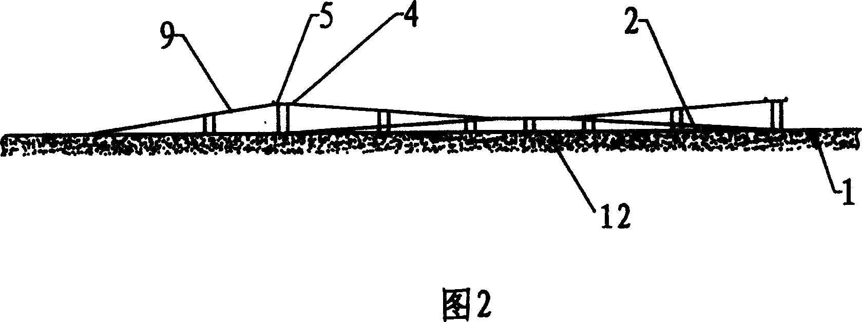
[0032] Because the ramp length of the curved arch separation bridge 2 should meet the regulations on the slope of the automobile road, the space height distance between the arc section 25 of the U-shaped ring road 24 and the curved arch separation bridge 2 will be guaranteed again, so the U-shaped ring road The length of 24 just needs to be longer, in order to shorten the length of U-shaped ring road 24, carry out partial modification on the structure of embodiment 1, as shown in Figure 2, be about to the height that the arc section 25 of U-shaped ring road 24 builds exceeds The height of the connection platform 23 makes the upper and lower U-shaped ring roads 24 combined to form a saddle shape like riding on the main road 1 . For this reason when entering the U-shaped ring road 24 from the connection platform 23, it is an uphill, and it is a downhill from the U-shaped ring road 24 to enter the connection platform 23, thereby the length of the U-shaped ring road 24 can be short...
Embodiment 3
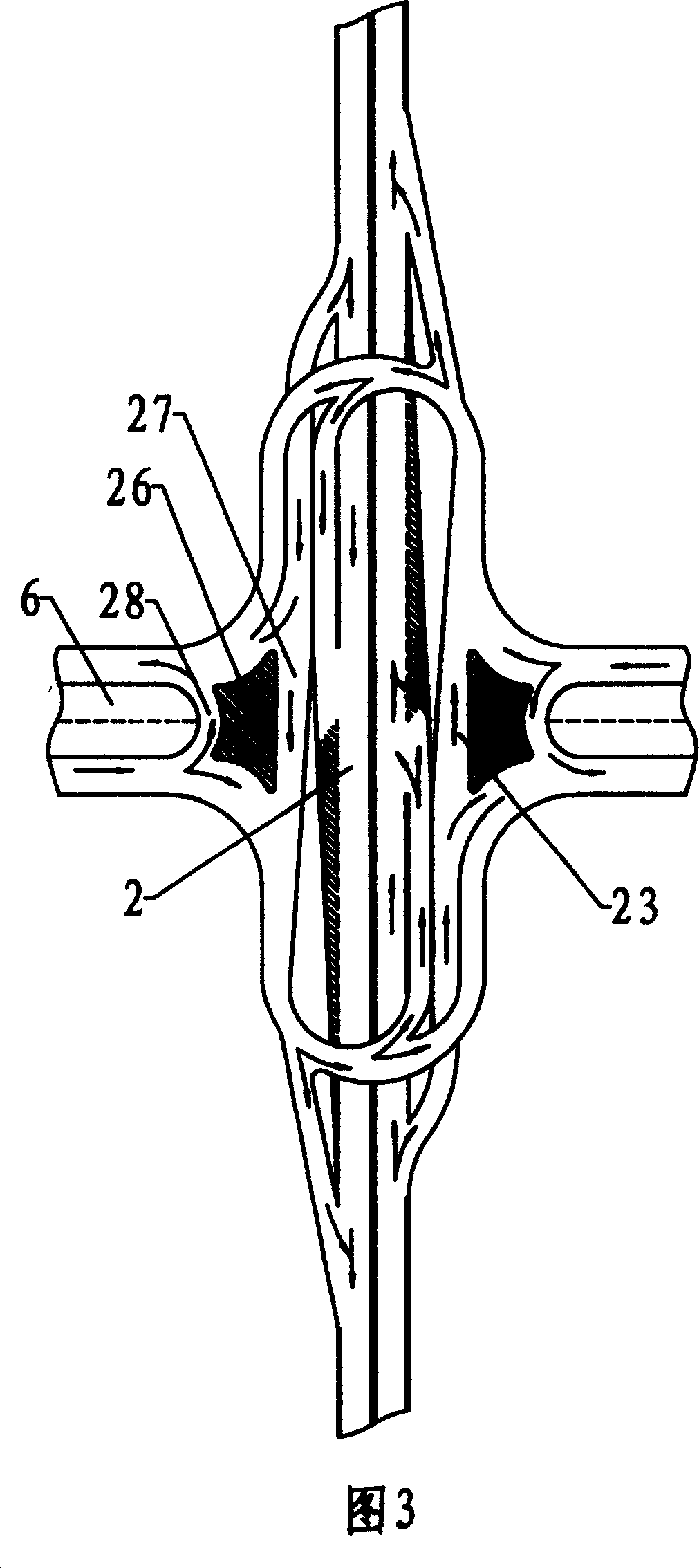
[0035] As shown in FIG. 3 , on the basis of the structure of Embodiment 1 and Embodiment 2, in order to reduce the U-turn distance of vehicles on the crossed road 3 , U-turn isolation belts 26 are respectively arranged on the left and right connecting platforms 23 . The U-turn isolation belt 26 divides the connecting platform 23 into a straight transition lane 27 and a U-turn lane 28 between the upper U-shaped ring road 24 and the lower U-shaped ring road 24, which satisfies the requirements of the upper U-shaped ring road 24 and the lower U-shaped ring road. Going straight between 24 makes the vehicle that needs to turn around on the crossed road 3 drive on the connecting platform 23 from the entrance driveway, and then turn around and drive into the exit driveway through the turnaround driveway 28, reducing the detour on the U-shaped ring road 24.
[0036] If the topographical conditions permit or the needs of traffic development, as shown in Figure 3, an underpass tunnel 6 c...
PUM
 Abstract
Description
Claims
Application Information
 - R&D
- Intellectual Property
- Life Sciences
- Materials
- Tech Scout
- Unparalleled Data Quality
- Higher Quality Content
- 60% Fewer Hallucinations
Browse by: Latest US Patents, China's latest patents, Technical Efficacy Thesaurus, Application Domain, Technology Topic, Popular Technical Reports.
© 2025 PatSnap. All rights reserved.Legal|Privacy policy|Modern Slavery Act Transparency Statement|Sitemap|About US| Contact US: help@patsnap.com